Part 1
요약·해설
지원표 9행, 공식 이미지와 5개 command block, 원문 XIAO BLE 오기를 보존했습니다.
Cortex-M7 · 480MHz
2M flash · ~1M SRAM
SPI · QSPI · microSD
USB CDC ACM
Part 2
접을 수 있는 영어 원문 전체
영어 원문 전체 펼치기
BC59D9679226123F6BB4BDA0E8DB71EA2EAC159F87497DDA3DBC6A1A5361E752
.. mini_stm32h743:

WeAct Studio MiniSTM32H743 Core Board
#####################################

Overview
********

The MiniSTM32H743 Core board is a compact development board equipped with
an STM32H743VIT6 microcontroller. It features a variety of peripherals,
including a user LED and button, a display, and external SPI and QuadSPI
NOR flash memory.

Key Features

- STM32 microcontroller in LQFP100 package
- USB OTG or full-speed device
- 1 user LED
- User, boot, and reset push-buttons
- 32.768 kHz and 25MHz HSE crystal oscillators
- External NOR Flash memories: 64-Mbit Quad-SPI and 64-Mbit SPI
- Board connectors:
   - Camera (8 bit) connector
   - ST7735 TFT-LCD 160 x 80 pixels (RGB565 3-SPI)
   - microSD |trade| card
   - USB Type-C Connector
   - SWD header for external debugger
   - 2x 40-pin GPIO connector

.. figure:: ../../../../../../../boards/weact/mini_stm32h743/doc/img/stm32h7xx.webp
      :align: center
      :alt: MiniSTM32H743 Core Board

      MiniSTM32H743 Core Board (Credit: WeAct Studio)

More information about the board can be found on the `Mini_STM32H743 website`_.

Hardware
********

The MiniSTM32H743 Core board provides the following hardware components:

- STM32H743VIT6 in LQFP100 package
- ARM 32-bit Cortex-M7 CPU with FPU
- Chrom-ART Accelerator
- Hardware JPEG Codec
- 480 MHz max CPU frequency
- VDD from 1.62 V to 3.6 V
- 2 MB Flash
- ~1 MB SRAM
- High-resolution timer (2.1 ns)
- 32-bit timers(2)
- 16-bit timers(10)
- SPI(6)
- I2C(4)
- I2S (3)
- USART(4)
- UART(4)
- USB OTG Full Speed and High Speed(1)
- USB OTG Full Speed(1)
- CAN FD(2)
- SAI(4)
- SPDIF_Rx(4)
- HDMI_CEC(1)
- Dual Mode Quad SPI(1)
- Camera Interface
- GPIO (up to 82) with external interrupt capability
- 16-bit ADC(3) with 16 channels
- 12-bit DAC with 2 channels(2)
- True Random Number Generator (RNG)
- 16-channel DMA
- LCD-TFT Controller with XGA resolution

More information about STM32H743 can be found here:

- `STM32H743VI on www.st.com`_
- `STM32H743/753 reference manual`_
- `STM32H743VI datasheet`_

Supported Features
==================

The mini_stm32h743 board configuration supports the following hardware features:

+-----------+------------+-------------------------------------+
| Interface | Controller | Driver/Component                    |
+===========+============+=====================================+
| NVIC      | on-chip    | nested vector interrupt controller  |
+-----------+------------+-------------------------------------+
| WDT       | on-chip    | watchdog                            |
+-----------+------------+-------------------------------------+
| PINMUX    | on-chip    | pinmux                              |
+-----------+------------+-------------------------------------+
| FLASH     | on-chip    | flash memory                        |
+-----------+------------+-------------------------------------+
| GPIO      | on-chip    | gpio                                |
+-----------+------------+-------------------------------------+
| SPI       | on-chip    | spi                                 |
+-----------+------------+-------------------------------------+
| QSPI NOR  | on-chip    | off-chip flash                      |
+-----------+------------+-------------------------------------+
| SDMMC     | on-chip    | disk access                         |
+-----------+------------+-------------------------------------+
| DISPLAY   | on-chip    | display                             |
+-----------+------------+-------------------------------------+

Other hardware features have not been enabled yet for this board.

The default configuration per core can be found in the defconfig file:
``boards/weact/mini_stm32h743/mini_stm32h743_defconfig``

Pin Mapping
===========

MiniSTM32H743 Core board has 5 GPIO controllers. These controllers are responsible for pin muxing,
input/output, pull-up, etc.

For more details please refer to `Mini_STM32H743 website`_.

Default Zephyr Peripheral Mapping:
----------------------------------

The MiniSTM32H743 Core board is configured as follows

- USER_LED : PE3
- USER_PB : PC13
- SPI1 SCK/MISO/MOSI/NSS : PB3/PB4/PD7/PD6 (NOR Flash memory)
- SPI4 SCK/MOSI/NSS : PE12/PE14/PE11 (LCD)
- QuadSPI CLK/NCS/IO0/IO1/IO2/IO3 : PB2/PB6/PD11/PD12/PE2/PD13 (NOR Flash memory)
- SDMMC1 CLK/DCMD/CD/D0/D1/D2/D3 : PC12/PD2/PD4/PC8/PC9/PC10/PC11 (microSD card)
- USB DM/DP : PA11/PA12 (USB CDC ACM)

System Clock
============

The STM32H743VI System Clock can be driven by an internal or external oscillator,
as well as by the main PLL clock. By default, the System clock is driven
by the PLL clock at 240MHz. PLL clock is fed by a 25MHz high speed external clock.

Serial Port (USB CDC ACM)
=========================

The Zephyr console output is assigned to the USB CDC ACM virtual serial port.
Virtual COM port interface. Default communication settings are 115200 8N1.

Programming and Debugging
*************************

The MiniSTM32H743 Core board facilitates firmware flashing via the USB DFU
bootloader. This method simplifies the process of updating images, although
it doesn't provide debugging capabilities. However, the board provides header
pins for the Serial Wire Debug (SWD) interface, which can be used to connect
an external debugger, such as ST-Link.

Flashing
========

To activate the bootloader, follow these steps:

1. Press and hold the BOOT0 key.
2. While still holding the BOOT0 key, press and release the RESET key.
3. Wait for 0.5 seconds, then release the BOOT0 key.

Upon successful execution of these steps, the device will transition into
bootloader mode and present itself as a USB DFU Mode device. You can program
the device using the west tool or the STM32CubeProgrammer.

Flashing an application to MiniSTM32H743
----------------------------------------

Here is an example for the :ref:`hello_world` application.

First, put the board in bootloader mode as described above. Then build and flash
the application in the usual way. Just add ``CONFIG_BOOT_DELAY=5000`` to the
configuration, so that USB CDC ACM is initialized before any text is printed,
as below:

.. zephyr-app-commands::
   :zephyr-app: samples/hello_world
   :board: mini_stm32h743
   :goals: build flash
   :gen-args: -DCONFIG_BOOT_DELAY=5000

Run a serial host program to connect with your board:

.. code-block:: console

   $ minicom -D <tty_device> -b 115200

Then, press the RESET button, you should see the following message after few seconds:

.. code-block:: console

   Hello World! mini_stm32h743

Replace :code:`<tty_device>` with the port where the board XIAO BLE
can be found. For example, under Linux, :code:`/dev/ttyACM0`.

Debugging
---------

This current Zephyr port does not support debugging.

Testing the LEDs in the MiniSTM32H743
*************************************

There is a sample that allows to test that LED on the board are working
properly with Zephyr:

.. zephyr-app-commands::
   :zephyr-app: samples/basic/blinky
   :board: mini_stm32h743
   :goals: build flash
   :gen-args: -DCONFIG_BOOT_DELAY=5000

You can build and flash the examples to make sure Zephyr is running correctly on
your board. The LED definitions can be found in
:zephyr_file:`boards/weact/mini_stm32h743/mini_stm32h743.dts`.

Testing shell over USB in the MiniSTM32H743
*******************************************

There is a sample that allows to test shell interface over USB CDC ACM interface
with Zephyr:

.. zephyr-app-commands::
   :zephyr-app: samples/subsys/shell/shell_module
   :board: mini_stm32h743
   :goals: build flash
   :gen-args: -DCONFIG_BOOT_DELAY=5000

.. _Mini_STM32H743 website:
   https://github.com/WeActStudio/MiniSTM32H7xx

.. _STM32H743VI on www.st.com:
   https://www.st.com/en/microcontrollers-microprocessors/stm32h743vi.html#overview

.. _STM32H743/753 reference manual:
   https://www.st.com/resource/en/reference_manual/rm0433-stm32h742-stm32h743753-and-stm32h750-value-line-advanced-armbased-32bit-mcus-stmicroelectronics.pdf

.. _STM32H743VI datasheet:
   https://www.st.com/resource/en/datasheet/stm32h743vi.pdf
Part 3
한국어 전문 번역
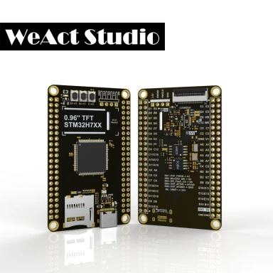
개요
MiniSTM32H743 Core는 STM32H743VIT6 microcontroller를 사용한 compact development board입니다. User LED·button, display, external SPI·QuadSPI NOR flash를 포함합니다.
주요 기능
- LQFP100 STM32 MCU
- USB OTG 또는 full-speed device
- User LED 1개와 user·boot·reset button
- 32.768kHz와 25MHz crystal oscillator
- 64-Mbit Quad-SPI와 64-Mbit SPI external NOR flash
- 8-bit camera connector
- 160×80 RGB565 3-SPI ST7735 TFT-LCD
- microSD card
- USB Type-C
- External debugger용 SWD header
- 40-pin GPIO connector 2개
하드웨어
- LQFP100 STM32H743VIT6
- FPU가 있는 ARM 32-bit Cortex-M7
- Chrom-ART accelerator와 hardware JPEG codec
- 최대 480MHz, VDD 1.62~3.6V
- Flash 2MB, SRAM 약 1MB
- 2.1ns high-resolution timer, 32-bit timer 2개, 16-bit timer 10개
- SPI 6개, I2C 4개, I2S 3개, USART 4개, UART 4개
- USB OTG FS/HS와 별도 USB OTG FS
- CAN FD 2개, SAI 4개, SPDIF_Rx 4개, HDMI_CEC
- Dual-mode QuadSPI, camera interface
- External interrupt GPIO 최대 82개
- 16-channel 16-bit ADC 3개, 2-channel 12-bit DAC 2개
- True RNG, 16-channel DMA, XGA LCD-TFT controller
지원 기능
| Interface | Controller | Driver/Component |
|---|---|---|
| NVIC | on-chip | nested vector interrupt controller |
| WDT | on-chip | watchdog |
| PINMUX | on-chip | pinmux |
| FLASH | on-chip | flash memory |
| GPIO | on-chip | gpio |
| SPI | on-chip | spi |
| QSPI NOR | on-chip | off-chip flash |
| SDMMC | on-chip | disk access |
| DISPLAY | on-chip | display |
그 밖의 기능은 아직 활성화되지 않았습니다. Default configuration은 boards/weact/mini_stm32h743/mini_stm32h743_defconfig에 있습니다.
Pin mapping
GPIO controller 5개가 pin muxing, I/O, pull-up 등을 담당합니다.
- USER_LED: PE3
- USER_PB: PC13
- SPI1 SCK/MISO/MOSI/NSS: PB3/PB4/PD7/PD6, NOR flash
- SPI4 SCK/MOSI/NSS: PE12/PE14/PE11, LCD
- QuadSPI CLK/NCS/IO0/IO1/IO2/IO3: PB2/PB6/PD11/PD12/PE2/PD13
- SDMMC1 CLK/DCMD/CD/D0/D1/D2/D3: PC12/PD2/PD4/PC8/PC9/PC10/PC11
- USB DM/DP: PA11/PA12, USB CDC ACM
System clock
System clock은 internal·external oscillator 또는 main PLL로 구동할 수 있습니다. Default는 25MHz HSE를 입력받는 PLL의 240MHz입니다.
Serial port(USB CDC ACM)
Zephyr console은 USB CDC ACM virtual serial port에 할당되며 default는 115200 8N1입니다.
Programming과 debugging
USB DFU bootloader로 firmware를 flash할 수 있지만 debug 기능은 없습니다. SWD header에는 ST-Link 같은 external debugger를 연결할 수 있습니다.
Bootloader 진입
- BOOT0 key를 누른 채 유지합니다.
- BOOT0을 누른 상태에서 RESET key를 눌렀다 놓습니다.
- 0.5초 기다린 뒤 BOOT0을 놓습니다.
성공하면 USB DFU Mode device로 나타나며 west 또는 STM32CubeProgrammer로 program할 수 있습니다.
Application flash
USB CDC ACM이 text 출력 전에 초기화되도록 CONFIG_BOOT_DELAY=5000을 추가합니다.
west build -b mini_stm32h743 -DCONFIG_BOOT_DELAY=5000 samples/hello_world
west flash
minicom -D <tty_device> -b 115200Hello World! mini_stm32h743Debug
현재 Zephyr port는 debugging을 지원하지 않습니다.
LED 시험
west build -b mini_stm32h743 -DCONFIG_BOOT_DELAY=5000 samples/basic/blinky
west flash
LED 정의는 boards/weact/mini_stm32h743/mini_stm32h743.dts에 있습니다.
USB shell 시험
west build -b mini_stm32h743 -DCONFIG_BOOT_DELAY=5000 samples/subsys/shell/shell_module
west flash
참고 자료
Source
출처
영어 원문에는 문단, 문서 지시문, 표, 코드, 코드 심벌, 경로를 그대로 보존했습니다.