Part 1
요약·해설
지원표 10행, 공식 이미지 2개와 V2.0 MISO 예외·84/42MHz clock을 보존했습니다.
Cortex-M4F · 84MHz
512K flash · 96K SRAM
42MHz clock
DFU · SWD
Part 2
접을 수 있는 영어 원문 전체
영어 원문 전체 펼치기
3A9A51F8040A08BD6B69843E8D50D62CC4405C153007DBC3F19CDD666E928C25
.. _blackpill_f401ce:

WeAct Studio Black Pill V3.0
############################

Overview
********

The WeAct Black Pill V3.0 Board is an extremely low cost and bare-bones
development board featuring the STM32F401CE, see `STM32F401CE website`_.
This is the 48-pin variant of the STM32F401x series,
see `STM32F401x reference manual`_. More info about the board available
`here <stm32-base-board-page_>`_ and on `WeAct Github`_.

.. image:: ../../../../../../../boards/weact/blackpill_f401ce/doc/img/blackpill-v3.jpg
      :align: center
      :alt: Black Pill V3.0+

Hardware
********

The STM32F401CE based Black Pill V3.0+ Board provides the following
hardware components:

- STM32F401CEU6 in UFQFPN48 package
- ARM |reg| 32-bit Cortex |reg| -M4 CPU with FPU
- 84 MHz max CPU frequency
- VDD from 1.7 V to 3.6 V
- 512 KB Flash
- 96 KB SRAM
- GPIO with external interrupt capability
- 1x12-bit, 2.4 MSPS ADC with 16 channels
- DMA Controller
- Up to 11 Timers (six 16-bit, two 32-bit, two watchdog timers and a SysTick timer)
- USART/UART (3)
- I2C (3)
- SPI/I2S (5)
- SDIO
- USB 2.0 full-speed device/host/OTG controller with on-chip PHY
- CRC calculation unit
- 96-bit unique ID
- RTC

Supported Features
==================

The Zephyr blackpill_f401ce board configuration supports the following
hardware features:

+------------+------------+-------------------------------------+
| Interface  | Controller | Driver/Component                    |
+============+============+=====================================+
| NVIC       | on-chip    | nested vector interrupt controller  |
+------------+------------+-------------------------------------+
| SYSTICK    | on-chip    | system clock                        |
+------------+------------+-------------------------------------+
| UART       | on-chip    | serial port                         |
+------------+------------+-------------------------------------+
| GPIO       | on-chip    | gpio                                |
+------------+------------+-------------------------------------+
| PINMUX     | on-chip    | pinmux                              |
+------------+------------+-------------------------------------+
| FLASH      | on-chip    | flash                               |
+------------+------------+-------------------------------------+
| SPI        | on-chip    | spi                                 |
+------------+------------+-------------------------------------+
| I2C        | on-chip    | i2c                                 |
+------------+------------+-------------------------------------+
| ADC        | on-chip    | ADC Controller                      |
+------------+------------+-------------------------------------+
| USB OTG FS | on-chip    | USB device                          |
+------------+------------+-------------------------------------+

The default configuration can be found in
:zephyr_file:`boards/weact/blackpill_f401ce/blackpill_f401ce_defconfig`

Pin Mapping
===========

Available pins:
---------------
.. image:: ../../../../../../../boards/weact/blackpill_f401ce/doc/img/Blackpill_Pinout.jpg
      :align: center
      :alt: Black Pill V3.0+ Pinout

Default Zephyr Peripheral Mapping:
----------------------------------

- UART_1 TX/RX : PA9/PA10
- I2C1 SCL/SDA : PB8/PB9
- SPI1 CS/SCK/MISO/MOSI : PA4/PA5/PA6/PA7 (Routed to footprint for external flash)
- PWM_4_CH1 : PB6
- PWM_4_CH2 : PB7
- ADC_1 : PA1
- USER_PB : PA0
- USER_LED : PC13

Note on SPI pin mapping: According to the `board release notes`_, there was a brief
change for V2.0 specifically where MISO was routed to PB4 for the flash footprint.
This was reverted for V2.1+ so that the flash DO pin was routed back to PA6. If using
V2.0 and en external flash, the pinmux will need to be modified accordingly.

Clock Sources
-------------

The board has two external oscillators. The frequency of the slow clock (LSE) is
32.768 kHz. The frequency of the main clock (HSE) is 25 MHz.

The default configuration sources the system clock from the PLL, which is
derived from HSE, and is set at 84MHz, which is the maximum possible frequency
to achieve a stable USB clock (42MHz).

Programming and Debugging
*************************

There are 2 main entry points for flashing STM32F4X SoCs, one using the ROM
bootloader, and another by using the SWD debug port (which requires additional
hardware). Flashing using the ROM bootloader requires a special activation
pattern, which can be triggered by using the BOOT0 pin.

Flashing
========

Installing dfu-util
-------------------

It is recommended to use at least v0.8 of `dfu-util`_. The package available in
debian/ubuntu can be quite old, so you might have to build dfu-util from source.

There is also a Windows version which works, but you may have to install the
right USB drivers with a tool like `Zadig`_.

Flashing an Application
-----------------------

Connect a USB-C cable and the board should power ON. Force the board into DFU mode
by keeping the BOOT0 switch pressed while pressing and releasing the NRST switch.

The dfu-util runner is supported on this board and so a sample can be built and
tested easily.

.. zephyr-app-commands::
   :zephyr-app: samples/basic/blinky
   :board: blackpill_f401ce
   :goals: build flash

Debugging
=========

The board can be debugged by installing the included 100 mil (0.1 inch) header,
and attaching an SWD debugger to the 3V3 (3.3V), GND, SCK, and DIO
pins on that header.

References
**********

.. target-notes::

.. _board release notes:
   https://github.com/WeActStudio/WeActStudio.MiniSTM32F4x1/blob/master/HDK/README.md

.. _Zadig:
   https://zadig.akeo.ie/

.. _WeAct Github:
   https://github.com/WeActStudio/WeActStudio.MiniSTM32F4x1

.. _stm32-base-board-page:
   https://stm32-base.org/boards/STM32F401CEU6-WeAct-Black-Pill-V3.0.html

.. _dfu-util:
   http://dfu-util.sourceforge.net/build.html

.. _STM32F401CE website:
   https://www.st.com/en/microcontrollers/stm32f401ce.html

.. _STM32F401x reference manual:
   https://www.st.com/resource/en/reference_manual/dm00096844.pdf
Part 3
한국어 전문 번역

개요
WeAct Black Pill V3.0는 STM32F401CE를 사용한 매우 저렴하고 최소 구성의 development board입니다. STM32F401x series의 48-pin variant입니다.
하드웨어
- UFQFPN48 package STM32F401CEU6
- FPU가 있는 ARM 32-bit Cortex-M4
- 최대 84MHz CPU, VDD 1.7~3.6V
- Flash 512KB, SRAM 96KB
- External interrupt-capable GPIO
- 16-channel 12-bit 2.4MSPS ADC 1개
- DMA controller
- Timer 최대 11개: 16-bit 6개, 32-bit 2개, watchdog 2개, SysTick
- USART/UART 3개, I2C 3개, SPI/I2S 5개
- SDIO
- On-chip PHY가 있는 USB 2.0 full-speed device/host/OTG
- CRC unit, 96-bit unique ID, RTC
지원 기능
| Interface | Controller | Driver/Component |
|---|---|---|
| NVIC | on-chip | nested vector interrupt controller |
| SYSTICK | on-chip | system clock |
| UART | on-chip | serial port |
| GPIO | on-chip | gpio |
| PINMUX | on-chip | pinmux |
| FLASH | on-chip | flash |
| SPI | on-chip | spi |
| I2C | on-chip | i2c |
| ADC | on-chip | ADC Controller |
| USB OTG FS | on-chip | USB device |
Default configuration은 boards/weact/blackpill_f401ce/blackpill_f401ce_defconfig에 있습니다.
Pin mapping
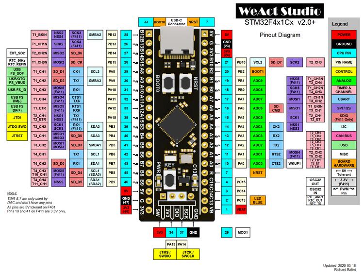
Default Zephyr peripheral mapping
- UART_1 TX/RX: PA9/PA10
- I2C1 SCL/SDA: PB8/PB9
- SPI1 CS/SCK/MISO/MOSI: PA4/PA5/PA6/PA7, external flash footprint로 routing
- PWM_4_CH1: PB6
- PWM_4_CH2: PB7
- ADC_1: PA1
- USER_PB: PA0
- USER_LED: PC13
Clock source
External oscillator가 두 개 있습니다. LSE slow clock은 32.768kHz, HSE main clock은 25MHz입니다. Default system clock은 HSE에서 유도한 PLL의 84MHz이며 안정적인 42MHz USB clock을 얻기 위한 설정입니다.
Programming과 debugging
STM32F4X flash 진입점은 ROM bootloader와 추가 hardware가 필요한 SWD debug port 두 가지입니다. ROM bootloader는 BOOT0 pin으로 activation pattern을 넣습니다.
dfu-util 설치
dfu-util v0.8 이상을 권장합니다. Debian/Ubuntu package가 오래됐으면 source build가 필요할 수 있고 Windows에서는 Zadig로 USB driver를 설치해야 할 수 있습니다.
Application flash
USB-C cable을 연결하고 BOOT0 switch를 누른 상태에서 NRST를 눌렀다 놓아 DFU mode로 진입합니다.
west build -b blackpill_f401ce samples/basic/blinky
west flash
Debug
포함된 100mil(0.1-inch) header를 설치하고 SWD debugger를 3V3, GND, SCK, DIO pin에 연결합니다.
참고 자료
Source
출처
영어 원문에는 문단, 문서 지시문, 표, 코드, 코드 심벌, 경로를 그대로 보존했습니다.