Part 1
요약·해설
지원표 15행, 공식 이미지와 전체 UART1 overlay·Segger 절차를 보존했습니다.
nRF52833 M4F
Bluetooth LE
On-chip
UART1 overlay
Part 2
접을 수 있는 영어 원문 전체
영어 원문 전체 펼치기
58DC2A378A1EF2920FBF1EE7C26BE33969F228442E34BF6FACB5C0571C973488
.. _ubx_ninab4_nrf52833:

u-blox EVK NINA-B40x
####################

Overview
********

The u-blox NINA-B4 Evaluation Kit hardware is a Bluetooth low energy
module based on the Nordic Semiconductor nRF52833 ARM Cortex-M4F CPU
and has support for the following features:

* :abbr:`ADC (Analog to Digital Converter)`
* CLOCK
* FLASH
* :abbr:`GPIO (General Purpose Input Output)`
* :abbr:`I2C (Inter-Integrated Circuit)`
* :abbr:`MPU (Memory Protection Unit)`
* :abbr:`NVIC (Nested Vectored Interrupt Controller)`
* :abbr:`PWM (Pulse Width Modulation)`
* RADIO (Bluetooth Low Energy)
* :abbr:`RTC (nRF RTC System Clock)`
* Segger RTT (RTT Console)
* :abbr:`SPI (Serial Peripheral Interface)`
* :abbr:`UART (Universal asynchronous receiver-transmitter)`
* :abbr:`USB (Universal Serial Bus)`
* :abbr:`WDT (Watchdog Timer)`

.. figure:: ../../../../../../../boards/u-blox/ubx_evkninab4/doc/img/EVK-NINA-B406_Top_web.jpg

    EVK NINA-B4

More information about the NINA-B4 module and the EVK-NINA-B4 can be
found at `NINA-B40 product page`_ and `EVK-NINA-B4 product page`_.

Supported Features
==================

The ubx_evkninab4/nrf52833 board configuration supports the following
hardware features:

+-----------+------------+----------------------+
| Interface | Controller | Driver/Component     |
+===========+============+======================+
| ADC       | on-chip    | adc                  |
+-----------+------------+----------------------+
| CLOCK     | on-chip    | clock_control        |
+-----------+------------+----------------------+
| FLASH     | on-chip    | flash                |
+-----------+------------+----------------------+
| GPIO      | on-chip    | gpio                 |
+-----------+------------+----------------------+
| I2C(M)    | on-chip    | i2c                  |
+-----------+------------+----------------------+
| MPU       | on-chip    | arch/arm             |
+-----------+------------+----------------------+
| NVIC      | on-chip    | arch/arm             |
+-----------+------------+----------------------+
| PWM       | on-chip    | pwm                  |
+-----------+------------+----------------------+
| RADIO     | on-chip    | Bluetooth low energy |
+-----------+------------+----------------------+
| RTC       | on-chip    | system clock         |
+-----------+------------+----------------------+
| RTT       | Segger     | console              |
+-----------+------------+----------------------+
| SPI(M/S)  | on-chip    | spi                  |
+-----------+------------+----------------------+
| UART      | on-chip    | serial               |
+-----------+------------+----------------------+
| USB       | on-chip    | usb                  |
+-----------+------------+----------------------+
| WDT       | on-chip    | watchdog             |
+-----------+------------+----------------------+

Other hardware features have not been enabled yet for this board.
See `EVK-NINA-B4 product page`_ and `NINA-B40 Data Sheet`_
for a complete list of EVK NINA-B4 hardware features.

Connections and IOs
===================

LED
---

* LED0 (red) = P0.13
* LED1 (green) = P1.01
* LED2 (blue) = P1.00

Push buttons
------------

* BUTTON1 = SW1 = P1.01 (Shared with green LED)
* BUTTON2 = SW2 = P0.02

General information on module pin numbering
-------------------------------------------

The numbering of the pins on the module and EVK do not follow the GPIO
numbering on the nRF52833 SoC. Please see the `NINA-B40 Data Sheet`_ for
information on how to map NINA-B40 pins to the pin numbering on the
nRF52833 SoC.

The reason for this is the u-blox module family concept where different
modules share the same pinout and can be interchanged, see
`NINA module family Nested design`_.

Programming and Debugging
*************************

Applications for the ``ubx_evkninab4/nrf52833`` board configuration can be
built and flashed in the usual way (see :ref:`build_an_application`
and :ref:`application_run` for more details); however, the standard
debugging targets are not currently available.

Flashing
========

Build and flash applications as usual (see
:ref:`build_an_application` and :ref:`application_run` for more details)

Here is an example for the :ref:`hello_world` application.

Open a terminal program to the USB Serial Port installed when connecting
the board and listen for output.

Settings: 115200, 8N1, no flow control.

Then build and flash the application in the usual way.

.. zephyr-app-commands::
   :zephyr-app: samples/hello_world
   :board: ubx_evkninab4/nrf52833
   :goals: build flash

Debugging
=========

Refer to the :ref:`nordic_segger` page to learn about debugging  boards
containing a Nordic Semiconductor chip with a Segger IC.


Testing the LEDs and buttons in the EVK NINA-B40x
*************************************************

There are 2 samples that allow you to test that the buttons (switches)
and LEDs on the board are working properly with Zephyr:

.. code-block:: console

   samples/basic/blinky
   samples/basic/button

You can build and flash the examples to make sure Zephyr is running
correctly on your board. The button and LED definitions can be found in
:zephyr_file:`boards/u-blox/ubx_evkninab4/ubx_evkninab4_nrf52833.dts`.

Note that the buttons on the EVK-NINA-B4 are marked SW1 and SW2, which
are named sw0 and sw1 in the dts file.
Also note that the SW1 button and the green LED are connected on HW level.

Using UART1
***********

The following approach can be used when an application needs to use
more than one UART for connecting peripheral devices:

1. Add device tree overlay file to the main directory of your application:

   .. code-block:: devicetree

      &pinctrl {
         uart1_default: uart1_default {
            group1 {
               psels = <NRF_PSEL(UART_TX, 0, 14)>,
                       <NRF_PSEL(UART_RX, 0, 16)>;
            };
         };
         /* required if CONFIG_PM_DEVICE=y */
         uart1_sleep: uart1_sleep {
            group1 {
               psels = <NRF_PSEL(UART_TX, 0, 14)>,
                       <NRF_PSEL(UART_RX, 0, 16)>;
               low-power-enable;
            };
         };
      };

      &uart1 {
        compatible = "nordic,nrf-uarte";
        current-speed = <115200>;
        status = "okay";
        pinctrl-0 = <&uart1_default>;
        pinctrl-1 = <&uart1_sleep>;
        pinctrl-names = "default", "sleep";
      };

   In the overlay file above, pin P0.16 is used for RX and P0.14 is used for TX

2. Use the UART1 as ``DEVICE_DT_GET(DT_NODELABEL(uart1))``

Overlay file naming
===================

The file has to be named ``<board>.overlay`` and placed in the app main directory to be
picked up automatically by the device tree compiler.

Selecting the pins
==================

Pins can be configured in the board pinctrl file. To see the available mappings,
open the data sheet for the NINA-B4 at `NINA-B40 Data Sheet`_, Section 3 'Pin definition'.
In the table 7 select the pins marked 'GPIO_xx'.  Note that pins marked as 'Radio sensitive pin'
can only be used in under-10KHz applications. They are not suitable for 115200 speed of UART.

.. note:
  Pins are defined according to the "nRF52" pin number, not the module pad number.


References
**********

.. target-notes::

.. _NINA-B40 product page: https://www.u-blox.com/en/product/nina-b40-series-open-cpu
.. _EVK-NINA-B4 product page: https://www.u-blox.com/en/product/evk-nina-b4
.. _Nordic Semiconductor Infocenter: https://infocenter.nordicsemi.com
.. _J-Link Software and documentation pack: https://www.segger.com/jlink-software.html
.. _NINA-B40 Data Sheet: https://www.u-blox.com/en/docs/UBX-19049405
.. _NINA module family Nested design: https://www.u-blox.com/en/docs/UBX-17065600
Part 3
한국어 전문 번역
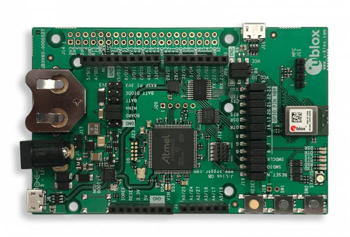
개요
u-blox NINA-B4 Evaluation Kit은 Nordic Semiconductor nRF52833 ARM Cortex-M4F CPU 기반 Bluetooth Low Energy module입니다. ADC, clock, flash, GPIO, I2C, MPU, NVIC, PWM, radio, RTC, Segger RTT, SPI, UART, USB, watchdog를 제공합니다.
NINA-B4 module과 EVK의 자세한 사양은 NINA-B40 제품 페이지와 EVK-NINA-B4 제품 페이지에서 확인할 수 있습니다.
지원 기능
ubx_evkninab4/nrf52833 board configuration은 다음 기능을 지원합니다.
| Interface | Controller | Driver/Component |
|---|---|---|
| ADC | on-chip | adc |
| CLOCK | on-chip | clock_control |
| FLASH | on-chip | flash |
| GPIO | on-chip | gpio |
| I2C(M) | on-chip | i2c |
| MPU | on-chip | arch/arm |
| NVIC | on-chip | arch/arm |
| PWM | on-chip | pwm |
| RADIO | on-chip | Bluetooth low energy |
| RTC | on-chip | system clock |
| RTT | Segger | console |
| SPI(M/S) | on-chip | spi |
| UART | on-chip | serial |
| USB | on-chip | usb |
| WDT | on-chip | watchdog |
그 밖의 기능은 아직 이 board에서 활성화되지 않았습니다. 전체 기능 목록은 EVK와 NINA-B40 data sheet를 참고합니다.
연결과 I/O
LED
- LED0(red) = P0.13
- LED1(green) = P1.01
- LED2(blue) = P1.00
Push button
- BUTTON1 = SW1 = P1.01, green LED와 공유
- BUTTON2 = SW2 = P0.02
Module pin 번호
Module과 EVK의 pin 번호는 nRF52833 SoC GPIO 번호를 따르지 않습니다. NINA-B40 data sheet에서 NINA-B40 pin과 nRF52833 pin의 대응을 확인해야 합니다. 서로 다른 module이 같은 pinout을 공유해 교체될 수 있도록 한 u-blox module family 개념 때문입니다.
Programming과 debugging
ubx_evkninab4/nrf52833 application은 일반적인 방식으로 build·flash할 수 있지만 standard debugging target은 현재 제공되지 않습니다.
Flash
Board를 연결할 때 설치되는 USB Serial Port를 terminal에서 열고 115200 baud, 8N1, flow control 없음으로 출력에 대기합니다.
west build -b ubx_evkninab4/nrf52833 samples/hello_world
west flash
Debug
Nordic Semiconductor chip과 Segger IC가 있는 board의 debug 방법은 Zephyr Nordic Segger 문서를 따릅니다.
EVK NINA-B40x의 LED와 button 시험
다음 두 sample로 switch와 LED가 Zephyr에서 제대로 동작하는지 시험할 수 있습니다.
samples/basic/blinky
samples/basic/button
정의는 boards/u-blox/ubx_evkninab4/ubx_evkninab4_nrf52833.dts에 있습니다. EVK의 SW1·SW2는 DTS에서 각각 sw0·sw1이며 SW1과 green LED는 hardware level에서 연결됩니다.
UART1 사용
Peripheral 연결에 UART가 하나 더 필요하면 application main directory에 device tree overlay를 추가합니다.
&pinctrl {
   uart1_default: uart1_default {
      group1 {
         psels = <NRF_PSEL(UART_TX, 0, 14)>,
                 <NRF_PSEL(UART_RX, 0, 16)>;
      };
   };
   /* required if CONFIG_PM_DEVICE=y */
   uart1_sleep: uart1_sleep {
      group1 {
         psels = <NRF_PSEL(UART_TX, 0, 14)>,
                 <NRF_PSEL(UART_RX, 0, 16)>;
         low-power-enable;
      };
   };
};

&uart1 {
  compatible = "nordic,nrf-uarte";
  current-speed = <115200>;
  status = "okay";
  pinctrl-0 = <&uart1_default>;
  pinctrl-1 = <&uart1_sleep>;
  pinctrl-names = "default", "sleep";
};
이 overlay는 P0.16을 RX, P0.14를 TX로 사용합니다. UART1은 DEVICE_DT_GET(DT_NODELABEL(uart1))로 얻습니다.
Overlay file 이름
Device tree compiler가 자동으로 찾도록 file 이름을 <board>.overlay로 지정하고 application main directory에 둡니다.
Pin 선택
Board pinctrl file에서 pin을 구성합니다. NINA-B40 data sheet section 3 Pin definition의 table 7에서 GPIO_xx 표시 pin을 고릅니다. Radio sensitive pin은 10kHz 미만 application에서만 사용할 수 있어 UART 115200에는 적합하지 않습니다.
참고 자료
Source
출처
영어 원문에는 문단, 문서 지시문, 표, 코드, 코드 심벌, 경로를 그대로 보존했습니다.