Part 1
요약·해설
지원표 13행, dual-core sharing 3방식, option byte와 M4 target 오기를 보존했습니다.
STM32H745XI
M7 + M4
480MHz
2MB / 1MB
Part 2
접을 수 있는 영어 원문 전체
영어 원문 전체 펼치기
341367629DA45AEBE8FDBB7247A02DC718F67C2B6AF16EEF5D378B66BEEA13A7
.. _stm32h745i_disco_board:

ST STM32H745I Discovery
#######################

Overview
********

The STM32H745I-DISCO Discovery kit is a complete demonstration and development
platform for STMicroelectronics Arm |reg| Cortex |reg|‑M7 and Cortex |reg|‑M4 core-based STM32H745XI microcontroller.

The full range of hardware features available on the board helps users enhance their application
development by an evaluation of almost all peripherals (such as USB OTG FS, Ethernet 10/100Mb/s,
eMMC, USART, SAI audio DAC stereo with audio jack input and output, MEMS digital microphone, SDRAM,
Quad-SPI flash memory, and RGB interface LCD with capacitive multi-touch panel). ARDUINO |reg| Uno V3
connectors provide easy connection to extension shields or daughterboards for specific applications.

STLINK-V3E is integrated into the board, as an embedded in-circuit debugger and programmer for the
STM32 MCU and the USB Virtual COM port bridge

Key Features

- Arm |reg| Cortex |reg| core-based microcontroller with 2 Mbytes of flash memory and 1 Mbyte of RAM, in a TFBGA240+25 package
- 4.3” RGB interface LCD with touch panel connector
- Ethernet compliant with IEEE-802.3-2002, and PoE
- USB OTG FS
- SAI audio codec
- One ST-MEMS digital microphone
- 2× 512-Mbit Quad-SPI NOR flash memory
- 128-Mbit SDRAM
- 4-Gbyte on-board eMMC
- 1 user and reset push-button
- Fanout daughterboard
- 2× CAN FDs
- Board connectors:

 - USB FS Micro-AB connectors
 - ST-LINK Micro-B USB connector
 - USB power Micro-B connector
 - Ethernet RJ45
 - Stereo headset jack including analog microphone input
 - Audio header for external speakers
 - Tag‑Connect |trade| (TAG) 10-pin footprint
 - Arm |reg| Cortex |reg| 10-pin 1.27 mm pitch debug connector over STDC14 footprint
 - ARDUINO |reg| Uno V3 expansion connectors
 - STMod+

- Flexible power-supply options:

 - STLINK-V3E USB connector, USB FS connector
 - 5 V delivered by RJ45 (Power over Ethernet)
 - 5 V delivered by ARDUINO |reg| or external connector
 - USB charger
 - USB power

.. image:: ../../../../../../../boards/st/stm32h745i_disco/doc/img/stm32h745i-disco.jpg
   :align: center
   :alt: STM32H745I-DISCO

More information about the board can be found at the `STM32H745I-DISCO website`_.
More information about STM32H747XIH6 can be found here:

- `STM32H745XI on www.st.com`_
- `STM32H745xx reference manual`_
- `STM32H745xx datasheet`_

Supported Features
==================

The current Zephyr stm32h745i_disco board configuration supports the following hardware features:

+-----------+------------+-------------------------------------+
| Interface | Controller | Driver/Component                    |
+===========+============+=====================================+
| NVIC      | on-chip    | nested vector interrupt controller  |
+-----------+------------+-------------------------------------+
| UART      | on-chip    | serial port                         |
+-----------+------------+-------------------------------------+
| PINMUX    | on-chip    | pinmux                              |
+-----------+------------+-------------------------------------+
| GPIO      | on-chip    | gpio                                |
+-----------+------------+-------------------------------------+
| RTC       | on-chip    | counter                             |
+-----------+------------+-------------------------------------+
| I2C       | on-chip    | i2c                                 |
+-----------+------------+-------------------------------------+
| PWM       | on-chip    | pwm                                 |
+-----------+------------+-------------------------------------+
| ETHERNET  | on-chip    | ethernet                            |
+-----------+------------+-------------------------------------+
| SPI       | on-chip    | spi                                 |
+-----------+------------+-------------------------------------+
| QSPI NOR  | on-chip    | off-chip flash                      |
+-----------+------------+-------------------------------------+
| FDCAN     | on-chip    | fdcan                               |
+-----------+------------+-------------------------------------+
| FMC       | on-chip    | memc (SDRAM)                        |
+-----------+------------+-------------------------------------+
| RTC       | on-chip    | rtc                                 |
+-----------+------------+-------------------------------------+

Other hardware features are not yet supported on this Zephyr port.

The default configuration per core can be found in the defconfig files:
:zephyr_file:`boards/st/stm32h745i_disco/stm32h745i_disco_stm32h745xx_m7_defconfig` and
:zephyr_file:`boards/st/stm32h745i_disco/stm32h745i_disco_stm32h745xx_m4_defconfig`

For more details please refer to `STM32H745-Disco UM`_.

Default Zephyr Peripheral Mapping:
----------------------------------

- USART_3 TX/RX : PB10/PB11 (ST-Link Virtual Port Com)
- USART_1 TX/RX : PB6/PB7 (Arduino Serial)
- SPI_2 NSS/SCK/MISO/MOSI : PB4/PD3/PI2/PB15 (Arduino SPI)
- I2C_4 SCL/SDA: PD12, PD13 (Arduino I2C)
- USER_PB : PC13
- LD1 : PI13
- LD2 : PJ2
- LD3 : PD3

System Clock
------------

STM32H745I-DISCO System Clock could be driven by an internal or external
oscillator, as well as the main PLL clock. By default, the System clock is
driven by the PLL clock at 480MHz, driven by an 25MHz high-speed external clock.

Serial Port
-----------

STM32H745I-DISCO board has 4 UARTs and 4 USARTs. The Zephyr console output is
assigned to UART3. Default settings are 115200 8N1.

Resources sharing
-----------------

The dual core nature of STM32H745 SoC requires sharing HW resources between the
two cores. This is done in 3 ways:

- **Compilation**: Clock configuration is only accessible to M7 core. M4 core only
  has access to bus clock activation and deactivation.
- **Static pre-compilation assignment**: Peripherals such as a UART are assigned in
  devicetree before compilation. The user must ensure peripherals are not assigned
  to both cores at the same time.
- **Run time protection**: Interrupt-controller and GPIO configurations could be
  accessed by both cores at run time. Accesses are protected by a hardware semaphore
  to avoid potential concurrent access issues.

Programming and Debugging
*************************

Applications for the ``stm32h745i_disco`` board should be built per core target,
using either ``stm32h745i_disco/stm32h745xx/m7`` or ``stm32h745i_disco/stm32h745xx/m4`` as the target
(see :ref:`build_an_application` and :ref:`application_run` for more details).

.. note::

   Check if the on-board ST-LINK V3 has the latest firmware version. It can be done with either `STM32CubeIDE`_ or `STM32CubeProgrammer`_

Flashing
========

STM32H745I-DISCO board includes an ST-LINK/V3 embedded debug tool interface.

Flashing operation will depend on the target and the SoC
option bytes configuration.

By default:

  - CPU0 (Cortex-M7) boot address is set to 0x80000000 (OB: BOOT_CM7_ADD0)
  - CPU1 (Cortex-M4) boot address is set to 0x81000000 (OB: BOOT_CM4_ADD0)

Also, the out of the box default board configuration enables CM7 and CM4 boot when
board is powered (Option bytes BCM7 and BCM4 are checked).
In that configuration, Kconfig boot option ``STM32H7_BOOT_CM4_CM7`` should be selected.
Zephyr flash configuration has been set to meet these default settings.

Alternatively, west `STM32CubeProgrammer`_ runner can be used, after installing
it, to flash applications for both cores. The target core is detected automatically.

.. code-block:: console

   $ west flash --runner stm32cubeprogrammer

Flashing an application to STM32H745XI M7 Core
----------------------------------------------
First, connect the STM32H745I-DISCO to your host computer using
the USB port to prepare it for flashing. Then build and flash your application.

Here is an example for the :ref:`hello_world` application.

Run a serial host program to connect with your STM32H745I-DISCO board.

.. code-block:: console

   $ minicom -b 115200 -D /dev/ttyACM0

or use screen:

.. code-block:: console

   $ screen /dev/ttyACM0 115200

Build and flash the application:

.. zephyr-app-commands::
   :zephyr-app: samples/hello_world
   :board: stm32h745i_disco/stm32h745xx/m7
   :goals: build flash

You should see the following message on the console:

.. code-block:: console

   $ Hello World! stm32h745i_disco

.. note::
  Sometimes, flashing does not work properly. It is necessary to erase the flash
  (with STM32CubeProgrammer for example) to make it work again.

Similarly, you can build and flash samples on the M4 target. For this, please
take care of the resource sharing (UART port used for console for instance).

Here is an example for the :zephyr:code-sample:`blinky` application on M4 core.

.. zephyr-app-commands::
   :zephyr-app: samples/basic/blinky
   :board: stm32h745i_disco/stm32h745xx/m7
   :goals: build flash

.. note::

   Flashing both M4 and M7 and pushing RESTART button on the board leads
   to LD1 and LD2 flashing simultaneously.

Debugging
=========

You can debug an application in the usual way.  Here is an example for the
:ref:`hello_world` application.

.. zephyr-app-commands::
   :zephyr-app: samples/hello_world
   :board: stm32h745i_disco/stm32h745xx/m7
   :maybe-skip-config:
   :goals: debug

Debugging with west is currently not available on Cortex M4 side.
In order to debug a Zephyr application on Cortex M4 side, you can use
`STM32CubeIDE`_.

.. _STM32H745I-DISCO website:
   https://www.st.com/en/evaluation-tools/stm32h745i-disco.html

.. _STM32H745XI on www.st.com:
   https://www.st.com/en/microcontrollers-microprocessors/stm32h745xi.html

.. _STM32H745xx reference manual:
   https://www.st.com/resource/en/reference_manual/rm0399-stm32h745755-and-stm32h747757-advanced-armbased-32bit-mcus-stmicroelectronics.pdf

.. _STM32H745xx datasheet:
   https://www.st.com/resource/en/datasheet/stm32h745xi.pdf

.. _STM32H745-Disco UM:
   https://www.st.com/resource/en/user_manual/um2488-discovery-kits-with-stm32h745xi-and-stm32h750xb-mcus-stmicroelectronics.pdf

.. _STM32CubeProgrammer:
   https://www.st.com/en/development-tools/stm32cubeprog.html

.. _STM32CubeIDE:
   https://www.st.com/en/development-tools/stm32cubeide.html
Part 3
한국어 전문 번역
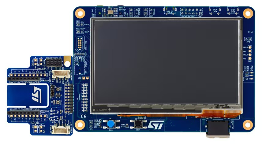
개요
STM32H745I-DISCO는 Cortex-M7+Cortex-M4 dual-core STM32H745XI를 위한 complete demonstration/development platform입니다. USB OTG FS, 10/100 Ethernet, eMMC, USART, stereo SAI audio, MEMS microphone, SDRAM, Quad-SPI, capacitive multi-touch RGB LCD 등을 평가하고 Arduino Uno V3 shield를 연결할 수 있습니다. STLINK-V3E는 debugger/programmer와 USB VCP bridge를 담당합니다.
주요 기능
- TFBGA240+25 dual-core MCU: Flash 2MB, RAM 1MB
- touch connector가 있는 4.3-inch RGB LCD
- IEEE-802.3-2002 Ethernet·PoE
- USB OTG FS
- SAI audio codec
- ST-MEMS digital microphone 1개
- 512Mbit Quad-SPI NOR Flash 2개
- 128Mbit SDRAM
- on-board eMMC 4GB
- USER·RESET button
- fanout daughterboard
- CAN FD 2개
- connector
- USB FS Micro-AB
- ST-LINK Micro-B
- USB power Micro-B
- Ethernet RJ45
- analog microphone input 포함 stereo headset
- external speaker audio header
- Tag-Connect 10-pin footprint
- STDC14 footprint의 Cortex 10-pin 1.27mm debug
- Arduino Uno V3
- STMod+
- 전원
- STLINK-V3E USB 또는 USB FS
- RJ45 PoE 5V
- Arduino/external 5V
- USB charger
- USB power
Zephyr 지원 기능
| Interface | Controller | Driver/Component |
|---|---|---|
| NVIC | on-chip | nested vector interrupt controller |
| UART | on-chip | serial port |
| PINMUX | on-chip | pinmux |
| GPIO | on-chip | gpio |
| RTC | on-chip | counter |
| I2C | on-chip | i2c |
| PWM | on-chip | pwm |
| ETHERNET | on-chip | ethernet |
| SPI | on-chip | spi |
| QSPI NOR | on-chip | off-chip flash |
| FDCAN | on-chip | fdcan |
| FMC | on-chip | memc (SDRAM) |
| RTC | on-chip | rtc |
원문은 RTC를 counter와 rtc 설명으로 두 번 기재합니다. core별 기본 설정은 stm32h745i_disco_stm32h745xx_m7_defconfig와 stm32h745i_disco_stm32h745xx_m4_defconfig입니다.
기본 Zephyr peripheral mapping
USART_3 TX/RX : PB10/PB11 (ST-Link Virtual Port Com)USART_1 TX/RX : PB6/PB7 (Arduino Serial)SPI_2 NSS/SCK/MISO/MOSI : PB4/PD3/PI2/PB15 (Arduino SPI)I2C_4 SCL/SDA : PD12/PD13 (Arduino I2C)USER_PB : PC13LD1 : PI13LD2 : PJ2LD3 : PD3
Clock·serial
기본 system clock은 25MHz HSE가 구동하는 PLL 480MHz입니다. UART 4개와 USART 4개가 있으며 Zephyr console은 UART3, 기본 통신은 115200 8N1입니다.
Resource sharing
dual-core SoC의 hardware resource 공유는 세 방식으로 관리합니다.
- Compilation: clock configuration은 M7만 접근하며 M4는 bus clock enable/disable만 접근합니다.
- Static pre-compilation assignment: UART 같은 peripheral을 devicetree에서 core별로 배정하고, 동시에 두 core에 배정하지 않도록 사용자가 보장합니다.
- Run-time protection: 두 core가 접근할 수 있는 interrupt-controller·GPIO configuration은 hardware semaphore로 concurrent access를 막습니다.
Programming and debugging
core별 target은 stm32h745i_disco/stm32h745xx/m7 또는 stm32h745i_disco/stm32h745xx/m4입니다. ST-LINK V3 firmware를 STM32CubeIDE/Programmer에서 최신으로 유지합니다.
Boot option
- CPU0 Cortex-M7: 0x80000000, BOOT_CM7_ADD0
- CPU1 Cortex-M4: 0x81000000, BOOT_CM4_ADD0
- 출고 상태는 BCM7·BCM4가 모두 checked되어 두 core boot
- 이 구성에서는 Kconfig STM32H7_BOOT_CM4_CM7 선택
STM32CubeProgrammer runner는 target core를 자동 감지합니다.
$ west flash --runner stm32cubeprogrammerM7 hello_world
$ minicom -b 115200 -D /dev/ttyACM0$ screen /dev/ttyACM0 115200west build -b stm32h745i_disco/stm32h745xx/m7 samples/hello_world
west flash$ Hello World! stm32h745i_discoFlash가 실패하면 STM32CubeProgrammer 등으로 erase해야 할 수 있습니다.
M4 blinky
west build -b stm32h745i_disco/stm32h745xx/m7 samples/basic/blinky
west flashDebug
west build -b stm32h745i_disco/stm32h745xx/m7 samples/hello_world
west debug
west의 Cortex-M4 debug는 지원되지 않으며 STM32CubeIDE를 사용합니다.
참고 자료
Source
출처
영어 원문에는 문단, 문서 지시문, 표, 코드, 코드 심벌, 경로를 그대로 보존했습니다.