Part 1
요약·해설
지원표 7행, board hardware와 UART 2개 mapping, ST-LINK flash/debug 및 Nucleo F030R8 제목 오기를 기록했습니다.
MCU
STM32F051R8T6
Memory
64KB / 8KB
Debug
ST-LINK/V2
UART
2 mappings
Part 2
접을 수 있는 영어 원문 전체
영어 원문 전체 펼치기
원문 SHA-256
D643CB9BB21D00A890918356BFAE9C5C9BD448FBC67694BA2162CA0256CF8594
.. _stm32f0_disco_board:

ST STM32F0 Discovery
####################

Overview
********

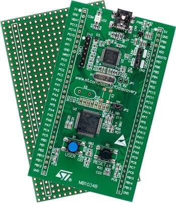
The STM32F0 Discovery development board uses an STM32F051R8T6 MCU and
integrates the ST-LINK/V2-1 debugger and programmer.  It also comes with a
comprehensive STM32 software HAL library and various packaged software
examples.

.. image:: ../../../../../../../boards/st/stm32f0_disco/doc/img/stm32f0_disco.jpg
     :align: center
     :alt: STM32F0DISCOVERY

More information about the board can be found at the `STM32F0DISCOVERY website`_.

Hardware
********

The STM32 Discovery board features:

- STM32F051R8T6 microcontroller featuring 64 KB Flash memory, 8 KB RAM in an
  LQFP64 package
- On-board ST-LINK/V2 with selection mode switch to use the kit as a standalone
  ST-LINK/V2 (with SWD connector for programming and debugging)
- Board power supply: through USB bus or from an external 5 V supply voltage
- External application power supply: 3 V and 5 V
- Four LEDs:

    - LD1 (red) for 3.3 V power on
    - LD2 (red/green) for USB communication
    - LD3 (green) for PC9 output
    - LD4 (blue) for PC8 output
- Two push buttons (user and reset)
- Extension header for all LQFP64 I/Os for quick connection to prototyping board
  and easy probing
- An additional board is provided which can be connected to the extension
  connector for even easier prototyping and probing.
- Comprehensive free software including a variety of examples, part of
  STM32CubeF0 package or STSW-STM32049 for legacy Standard Libraries usage

More information about STM32F051R8 can be found in the `STM32F0x8 reference manual`_.

Supported Features
==================

The Zephyr stm32f0_disco board configuration supports the following hardware features:

+-----------+------------+-------------------------------------+
| Interface | Controller | Driver/Component                    |
+===========+============+=====================================+
| NVIC      | on-chip    | nested vector interrupt controller  |
+-----------+------------+-------------------------------------+
| UART      | on-chip    | serial port-polling;                |
|           |            | serial port-interrupt               |
+-----------+------------+-------------------------------------+
| PINMUX    | on-chip    | pinmux                              |
+-----------+------------+-------------------------------------+
| GPIO      | on-chip    | gpio                                |
+-----------+------------+-------------------------------------+
| CLOCK     | on-chip    | reset and clock control             |
+-----------+------------+-------------------------------------+
| FLASH     | on-chip    | flash memory                        |
+-----------+------------+-------------------------------------+
| WATCHDOG  | on-chip    | independent watchdog                |
+-----------+------------+-------------------------------------+

Other hardware features are not yet supported in this Zephyr port.

The default configuration can be found in
:zephyr_file:`boards/st/stm32f0_disco/stm32f0_disco_defconfig`

Connections and IOs
===================

Each of the GPIO pins can be configured by software as output (push-pull or open-drain), as
input (with or without pull-up or pull-down), or as peripheral alternate function. Most of the
GPIO pins are shared with digital or analog alternate functions. All GPIOs are high current
capable except for analog inputs.

Default Zephyr Peripheral Mapping:
----------------------------------

- UART_1_TX : PA9
- UART_1_RX : PA10
- UART_2_TX : PA2
- UART_2_RX : PA3

For more details please refer to `STM32F0DISCOVERY board User Manual`_.

Programming and Debugging
*************************

Applications for the ``stm32f0_disco`` board configuration can be built and
flashed in the usual way (see :ref:`build_an_application` and
:ref:`application_run` for more details).

Flashing
========

STM32F0DISCOVERY board includes an ST-LINK/V2-1 embedded debug tool interface.
This interface is supported by the openocd version included in the Zephyr SDK.

Flashing an application to Nucleo F030R8
----------------------------------------

Here is an example for the :zephyr:code-sample:`blinky` application.

.. zephyr-app-commands::
   :zephyr-app: samples/basic/blinky
   :board: stm32f0_disco
   :goals: build flash

You will see the LED blinking every second.

Debugging
=========

You can debug an application in the usual way.  Here is an example for the
:zephyr:code-sample:`blinky` application.

.. zephyr-app-commands::
   :zephyr-app: samples/basic/blinky
   :board: stm32f0_disco
   :maybe-skip-config:
   :goals: debug

References
**********

.. target-notes::

.. _STM32F0DISCOVERY website:
   https://www.st.com/en/evaluation-tools/stm32f0discovery.html

.. _STM32F0x8 reference manual:
   https://www.st.com/resource/en/reference_manual/dm00031936.pdf

.. _STM32F0DISCOVERY board User Manual:
   https://www.st.com/resource/en/user_manual/dm00050135.pdf
Part 3
한국어 전문 번역
개요
STM32F0 Discovery는 STM32F051R8T6와 ST-LINK/V2-1을 통합하고 STM32 HAL library와 packaged example을 제공하는 development board입니다.
Hardware
- LQFP64 STM32F051R8T6: flash 64KB, RAM 8KB
- Standalone ST-LINK/V2로 전환 가능한 mode switch와 SWD connector
- USB bus 또는 external 5V board power, application용 3V·5V
- LED 4개
- LD1 red 3.3V power
- LD2 red/green USB communication
- LD3 green PC9
- LD4 blue PC8
- USER·RESET button
- 모든 LQFP64 I/O용 extension header
- 더 쉬운 prototyping·probing용 추가 board
- STM32CubeF0 example 또는 legacy Standard Library용 STSW-STM32049
Zephyr 지원 기능
| Interface | Controller | Driver/Component |
|---|---|---|
| NVIC | on-chip | nested vector interrupt controller |
| UART | on-chip | serial port-polling; serial port-interrupt |
| PINMUX | on-chip | pinmux |
| GPIO | on-chip | gpio |
| CLOCK | on-chip | reset and clock control |
| FLASH | on-chip | flash memory |
| WATCHDOG | on-chip | independent watchdog |
표 밖 기능은 아직 지원하지 않습니다. 기본 설정은 boards/st/stm32f0_disco/stm32f0_disco_defconfig입니다.
Connection과 I/O
각 GPIO는 push-pull/open-drain output, pull-up/pull-down 선택 input 또는 peripheral alternate function으로 설정할 수 있습니다. 대부분 digital/analog alternate function과 공유되며 analog input을 제외한 GPIO는 high-current capable입니다.
기본 Zephyr peripheral mapping
UART_1_TX : PA9UART_1_RX : PA10UART_2_TX : PA2UART_2_RX : PA3
Programming and debugging
On-board ST-LINK/V2-1은 Zephyr SDK의 OpenOCD가 지원합니다. 공식 원문의 flash section 제목은 이 board가 아닌 Nucleo F030R8이라고 적혀 있으므로 오기를 기록합니다.
Flashing
west build -b stm32f0_disco samples/basic/blinky
west flash
LED가 1초마다 깜빡입니다.
Debugging
west build -b stm32f0_disco samples/basic/blinky
west debug
참고 자료
Source
출처
영어 원문에는 문단, 문서 지시문, 표, 코드, 코드 심벌, 경로를 그대로 보존했습니다.