Part 1
요약·해설
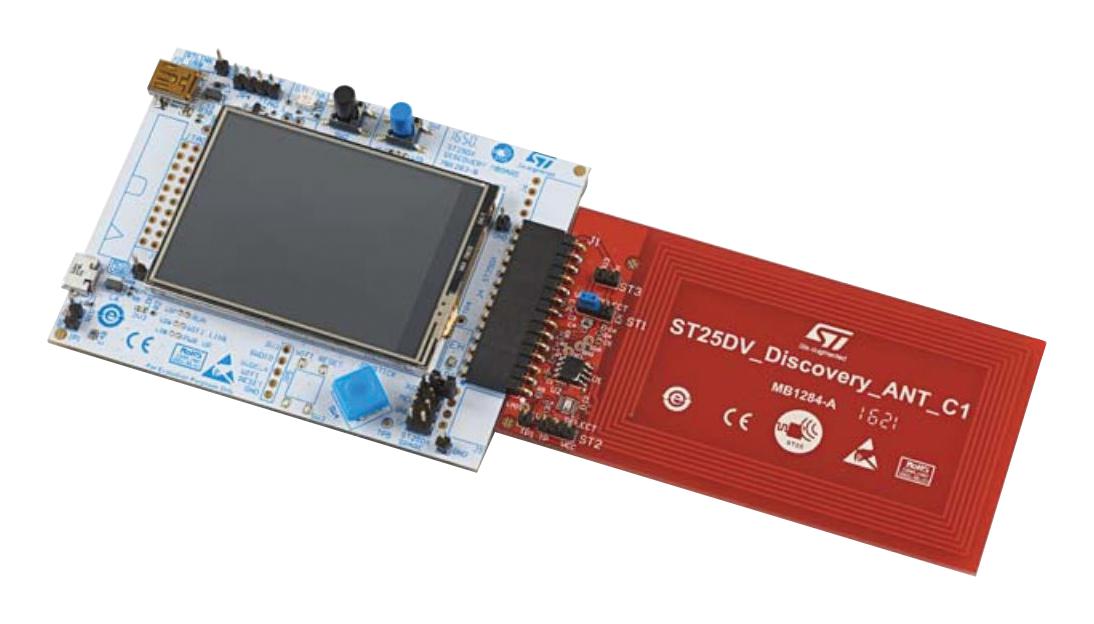
ST25DV 미구현 상태, MB1283/MB1285 main board와 Class 5 antenna, 전체 UART·I2C·SPI·GPIO mapping 및 reset flash workaround를 번역했습니다.
STM32F405VGT6
ST25DV04K
13.56MHz
Tag not implemented
Part 2
접을 수 있는 영어 원문 전체
영어 원문 전체 펼치기
CDF1171F1A204853977DD8A674FFEB82705FBBC5A6E9169A485CB408062CF3E8
.. _st25dv_mb1283_disco_board:

ST ST25DV Discovery, MB1283 version
###################################

Overview
********

The ST25DV04K device is a dynamic NFC/RFID tag IC with a dual interface. It embeds a
4 Kbits EEPROM memory. It can be operated from an I2C interface, or by a 13.56 MHz
RFID reader, or by a NFC phone. The ST25DV04K Class 5 antenna daughter card, included
in the kit, can be replaced by Class 1 or Class 6 antennas.

The ST25DV-DISCOVERY is a demonstration kit to evaluate the features and capabilities
of the ST25DV series.
It is based on the NFC ST25DV04K device embedded on a daughter card using a Class 5 antenna
and a STM32 processor driving a mother board.

.. image:: ../../../../../../../boards/st/st25dv_mb1283_disco/docs/img/st25dv_mb1283_disco.jpg
     :align: center
     :alt: ST25DV_MB1283_DISCO

.. note::
   The ST25DV itself is not implemented yet.

Hardware
********

The ST25DV Discovery kit provides the following hardware components:

- Main board: ST25DV_Discovery_Mboard:

  - STM32F405VGT6 LQFP100 32-bit microcontroller, with 1 Mbyte Flash memory, 192 + 4 Kbytes SRAM.
  - LCD color screen (320 x 200 pixels)
  - Touch screen driver
  - Different color LEDs (power, user, ST link)
  - User push button
  - Joystick for menu selection
  - Reset button
  - On board ST link for microcontroller firmware upgrade and debug
  - ST link mini USB
  - User micro USB
  - USB micro or mini connector for board powering
  - Demonstration edition (optional add-on module) with Bluetooth Low Energy module,
    Wi-Fi ® module and JTAG 20 pin connector

It exists in two variants, MB1283 and MB1285.

- Antenna daughter board: ST25DV_Discovery_ANT_C5:

  - 40 mm x 24 mm, 13.56 MHz inductive antenna etched on the PCB
  - ST25DV04K Dynamic NFC / RFID tag
  - I 2 C interface connector
  - Energy harvesting output (VOUT) with a 10nF capacitance filtering circuit
  - GPO configurable as RF WIP/BUSY output, to indicate that an RF operation is ongoing

The antenna board can be removed, and its 14-pin 0.254mm header connector used as an eval kit header.

Connections and IOs
===================

Default Zephyr Peripheral Mapping
---------------------------------

- UART_6 TX/RX : PC6/PC7 (ST-Link Virtual Port Com)
- UART_2 TX/RX : PA2/PA3 (Available on J6 connector)
- I2C1 SCL/SDA : PB6/PB7 (Touchscreen STMPE811, interrupt pin PB5)
- SPI2 SCK/MOSI/CS : PB13/PC3/PB12 (LCD display FRD24048TP, reset pin PC1, DC pin PC0)
- SPI1 SCK/MISO/MOSI/CS : PA5/PA6/PA7/PA4 (External ST25DV connector J6)
- GPIO : PE8/PE9/PE10/PE11/PE12 (Joystick)
- LD1 : PC13 (Orange led)
- LD2 : PC4 (Yellow led)
- GPIO : PE15/PE7 (Available on external ST25DV connector J6)
- GPIO : PE14 (Available on J5 connector)

Serial Port
===========

The Zephyr console output and shell are assigned to UART6, which is connected to the
onboard ST-LINK/V2 Virtual COM port interface.
Default communication settings are 115200 8N1.

Programming and Debugging
*************************

Applications for the ``st25dv_mb1283_disco`` board configuration can be built and
flashed in the usual way (see :ref:`build_an_application` and
:ref:`application_run` for more details).

If programming fails, press the reset button (black) and release it while "west flash" is running.

Flashing
========

ST25DV Discovery kit includes an ST-LINK/V2 embedded debug tool interface.
This interface is supported by the openocd version included in the Zephyr SDK.

Flashing an application to ST25DV Discovery
--------------------------------------------

First, connect the ST25DV Discovery kit to your host computer using
the USB port to prepare it for flashing. Then build and flash your application.

Here is an example for the :ref:`hello_world` application.

.. zephyr-app-commands::
   :zephyr-app: samples/hello_world
   :board: st25dv_mb1283_disco
   :goals: build flash

Run a serial host program to connect with your board:

.. code-block:: console

   $ minicom -D /dev/ttyACM0

You should see the following message on the console:

.. code-block:: console

   Hello World! st25dv_mb1283_disco

Debugging
=========

You can debug an application in the usual way. Here is an example for the
:ref:`hello_world` application.

.. zephyr-app-commands::
   :zephyr-app: samples/hello_world
   :board: st25dv_mb1283_disco
   :goals: debug


.. _ST25DV-DISCO website:
   https://www.st.com/en/nfc/st25dv-i2c-series-dynamic-nfc-tags.html

.. _ST25DV datasheet:
   https://www.st.com/resource/en/datasheet/st25dv04k.pdf

.. _STM32F40xxx reference manual:
   https://www.st.com/resource/en/reference_manual/rm0090-stm32f405415-stm32f407417-stm32f427437-and-stm32f429439-advanced-armbased-32bit-mcus-stmicroelectronics.pdf
Part 3
한국어 전문 번역
개요
ST25DV04K는 I2C, 13.56MHz RFID reader 또는 NFC phone으로 접근할 수 있는 dual-interface dynamic NFC/RFID tag IC이며 EEPROM 4Kbit를 내장합니다. Kit의 Class 5 antenna daughter card는 Class 1 또는 Class 6 antenna로 교체할 수 있습니다.
ST25DV-DISCOVERY는 STM32 기반 main board와 Class 5 antenna daughter card의 ST25DV04K로 ST25DV series의 기능을 평가하는 demonstration kit입니다.
지원 상태: ST25DV tag 자체는 이 Zephyr board port에서 아직 구현되지 않았습니다.
Hardware
- ST25DV_Discovery_Mboard
- LQFP100 STM32F405VGT6 32-bit MCU: flash 1MB, SRAM 192KB+4KB
- 320×200 color LCD와 touch-screen driver
- Power·user·ST-Link color LED, user button, menu joystick, reset button
- Firmware upgrade·debug용 on-board ST-Link와 ST-Link Mini-USB
- User Micro-USB 및 board power용 Micro/Mini connector
- Optional demonstration add-on: BLE module, Wi-Fi module, 20-pin JTAG
- Main board variant는 MB1283과 MB1285 두 종류
- ST25DV_Discovery_ANT_C5 antenna daughter board
- PCB에 식각한 40×24mm 13.56MHz inductive antenna
- ST25DV04K dynamic NFC/RFID tag
- I2C interface connector
- 10nF filtering circuit가 있는 energy-harvesting VOUT
- RF operation 진행 중을 알리는 RF WIP/BUSY output으로 설정 가능한 GPO
- Antenna board는 분리할 수 있으며 14-pin 0.254mm header를 evaluation-kit header로 사용
Connection과 I/O
기본 Zephyr peripheral mapping
UART_6 TX/RX : PC6/PC7 (ST-Link Virtual Port Com)UART_2 TX/RX : PA2/PA3 (J6)I2C1 SCL/SDA : PB6/PB7 (STMPE811 touchscreen, interrupt PB5)SPI2 SCK/MOSI/CS : PB13/PC3/PB12 (FRD24048TP LCD, reset PC1, DC PC0)SPI1 SCK/MISO/MOSI/CS : PA5/PA6/PA7/PA4 (external ST25DV J6)GPIO : PE8/PE9/PE10/PE11/PE12 (joystick)LD1 : PC13 (orange)LD2 : PC4 (yellow)GPIO : PE15/PE7 (external ST25DV J6)GPIO : PE14 (J5)
Serial port
Zephyr console과 shell은 ST-LINK/V2 Virtual COM에 연결된 UART6이며 기본값은 115200 8N1입니다.
Programming and debugging
st25dv_mb1283_disco application은 일반적인 방법으로 build·flash합니다. Programming이 실패하면 west flash가 실행 중일 때 검은 reset button을 눌렀다가 놓습니다. On-board ST-LINK/V2는 Zephyr SDK의 OpenOCD가 지원합니다.
Flashing
west build -b st25dv_mb1283_disco samples/hello_world
west flash
$ minicom -D /dev/ttyACM0Hello World! st25dv_mb1283_discoDebugging
west build -b st25dv_mb1283_disco samples/hello_world
west debug
참고 자료
Source
출처
영어 원문에는 문단, 문서 지시문, 표, 코드, 코드 심벌, 경로를 그대로 보존했습니다.