Part 1
요약·해설
지원표 16행, LoRa·FSK sensitivity와 +22dBm transmitter, security·dual-core IPC·pin mapping, sleep-compatible OpenOCD 주의를 보존했습니다.
STM32WL55JC
150~960MHz
M4 + M0+
256KB / 64KB
Part 2
접을 수 있는 영어 원문 전체
영어 원문 전체 펼치기
535B8742E565E2258F4FE1A03A3C358F9D481E220EDB03A639F1148B06E751F5
.. _nucleo_wl55jc_board:

ST Nucleo WL55JC
################

Overview
********

The NUCLEO-WL55JC STM32WL Nucleo-64 board provides an affordable and flexible
way for users to try out new concepts and build prototypes with the STM32WL
Series microcontroller, choosing from the various combinations of performance,
power consumption, and features.

- STM32WL55JC microcontroller multiprotocol LPWAN dual-core 32-bit
  (Arm® Cortex®-M4/M0+ at 48 MHz) in UFBGA73 package featuring:

  - Ultra-low-power MCU
  - RF transceiver (150 MHz to 960 MHz frequency range) supporting LoRa®,
    (G)FSK, (G)MSK, and BPSK modulations
  - 256-Kbyte Flash memory and 64-Kbyte SRAM

- 3 user LEDs
- 3 user buttons and 1 reset push-button
- 32.768 kHz LSE crystal oscillator
- 32 MHz HSE on-board oscillator
- Board connectors:

  - USB with Micro-B
  - MIPI debug connector
  - ARDUINO Uno V3 expansion connector
  - ST morpho extension pin headers for full access to all STM32WL I/Os

- Delivered with SMA antenna
- Flexible power-supply options: ST-LINK, USB VBUS, or external sources
- On-board STLINK-V3 debugger/programmer with USB re-enumeration capability:
  mass storage, Virtual COM port, and debug port
- Comprehensive free software libraries and examples available with the
  STM32CubeWL MCU Package
- Support of a wide choice of Integrated Development Environments (IDEs)
  including IAR Embedded Workbench®, MDK-ARM, and STM32CubeIDE
- Suitable for rapid prototyping of end nodes based on LoRaWAN, Sigfox, wM-Bus,
  and many other proprietary protocols
- Fully open hardware platform


.. image:: ../../../../../../../boards/st/nucleo_wl55jc/doc/img/nucleo_wl55jc.jpg
   :align: center
   :alt: Nucleo WL55JC

More information about the board can be found at the `Nucleo WL55JC website`_.

Hardware
********

The STM32WL55JC long-range wireless and ultra-low-power devices embed a powerful
and ultra-low-power LPWAN-compliant radio solution, enabling the following
modulations: LoRa®, (G)FSK, (G)MSK, and BPSK
It provides the following hardware capabilities:

- Radio

  - Frequency range: 150 MHz to 960 MHz
  - Modulation: LoRa®, (G)FSK, (G)MSK and BPSK
  - RX sensitivity: –123 dBm for 2-FSK(at 1.2 Kbit/s), –148 dBm for LoRa®
    (at 10.4 kHz, spreading factor 12)
  - Transmitter high output power, programmable up to +22 dBm
  - Transmitter low output power, programmable up to +15 dBm
  - Compliant with the following radio frequency regulations such as
    ETSI EN 300 220, EN 300 113, EN 301 166, FCC CFR 47 Part 15, 24, 90, 101
    and the Japanese ARIB STD-T30, T-67, T-108
  - Compatible with standardized or proprietary protocols such as LoRaWAN®,
    Sigfox™, W-MBus and more (fully open wireless system-on-chip)

- Core

  - 32-bit Arm® Cortex®-M4 CPU

    - Adaptive real-time accelerator (ART Accelerator) allowing 0-wait-state
      execution from Flash memory, frequency up to 48 MHz, MPU
      and DSP instructions
    - 1.25 DMIPS/MHz (Dhrystone 2.1)

  - 32-bit Arm®Cortex®-M0+ CPU

    - Frequency up to 48 MHz, MPU
    - 0.95 DMIPS/MHz (Dhrystone 2.1)

- Security and identification

  - Hardware encryption AES 256-bit
  - True random number generator (RNG)
  - Sector protection against read/write operations (PCROP, RDP, WRP)
  - CRC calculation unit
  - Unique device identifier (64-bit UID compliant with IEEE 802-2001 standard)
  - 96-bit unique die identifier
  - Hardware public key accelerator (PKA)
  - Key management services
  - Secure sub-GHz MAC layer
  - Secure firmware update (SFU)
  - Secure firmware install (SFI)

- Supply and reset management

  - High-efficiency embedded SMPS step-down converter
  - SMPS to LDO smart switch
  - Ultra-safe, low-power BOR (brownout reset) with 5 selectable thresholds
  - Ultra-low-power POR/PDR
  - Programmable voltage detector (PVD)
  - VBAT mode with RTC and 20x32-byte backup registers

- Clock sources

  - 32 MHz crystal oscillator
  - TCXO support: programmable supply voltage
  - 32 kHz oscillator for RTC with calibration
  - High-speed internal 16 MHz factory trimmed RC (± 1 %)
  - Internal low-power 32 kHz RC
  - Internal multi-speed low-power 100 kHz to 48 MHz RC
  - PLL for CPU, ADC and audio clocks

- Memories

  - 256-Kbyte Flash memory
  - 64-Kbyte RAM
  - 20x32-bit backup register
  - Bootloader supporting USART and SPI interfaces
  - OTA (over-the-air) firmware update capable
  - Sector protection against read/write operations

- Rich analog peripherals (down to 1.62 V)

  - 12-bit ADC 2.5 Msps, up to 16 bits with hardware oversampling,
    conversion range up to 3.6 V
  - 12-bit DAC, low-power sample-and-hold
  - 2x ultra-low-power comparators

- System peripherals

  - Mailbox and semaphores for communication between Cortex®-M4 and Cortex®-M0+
    firmware

- Controllers

  - 2x DMA controller (7 channels each) supporting ADC, DAC, SPI, I2C, LPUART,
    USART, AES and timers
  - 2x USART (ISO 7816, IrDA, SPI)
  - 1x LPUART (low-power)
  - 2x SPI 16 Mbit/s (1 over 2 supporting I2S)
  - 3x I2C (SMBus/PMBus™)
  - 2x 16-bit 1-channel timer
  - 1x 16-bit 4-channel timer (supporting motor control)
  - 1x 32-bit 4-channel timer
  - 3x 16-bit ultra-low-power timer
  - 1x RTC with 32-bit sub-second wakeup counter
  - 1x independent SysTick
  - 1x independent watchdog
  - 1x window watchdog

- Up to 43 I/Os, most 5 V-tolerant
- Development support
  - Serial-wire debug (SWD), JTAG
  - Dual CPU cross trigger capabilities


More information about STM32WL55JC can be found here:

- `STM32WL55JC on www.st.com`_
- `STM32WL55JC datasheet`_
- `STM32WL55JC reference manual`_

Supported Features
==================

The Zephyr nucleo_wl55jc board configuration supports the following hardware
features:

+-----------+------------+-------------------------------------+
| Interface | Controller | Driver/Component                    |
+===========+============+=====================================+
| AES       | on-chip    | crypto                              |
+-----------+------------+-------------------------------------+
| CLOCK     | on-chip    | reset and clock_control             |
+-----------+------------+-------------------------------------+
| FLASH     | on-chip    | flash                               |
+-----------+------------+-------------------------------------+
| GPIO      | on-chip    | gpio                                |
+-----------+------------+-------------------------------------+
| I2C       | on-chip    | i2c                                 |
+-----------+------------+-------------------------------------+
| MPU       | on-chip    | arch/arm                            |
+-----------+------------+-------------------------------------+
| NVIC      | on-chip    | arch/arm                            |
+-----------+------------+-------------------------------------+
| PINMUX    | on-chip    | pinmux                              |
+-----------+------------+-------------------------------------+
| RADIO     | on-chip    | LoRa                                |
+-----------+------------+-------------------------------------+
| RNG       | on-chip    | entropy                             |
+-----------+------------+-------------------------------------+
| SPI       | on-chip    | spi                                 |
+-----------+------------+-------------------------------------+
| UART      | on-chip    | serial port-polling;                |
|           |            | serial port-interrupt               |
+-----------+------------+-------------------------------------+
| ADC       | on-chip    | ADC Controller                      |
+-----------+------------+-------------------------------------+
| DAC       | on-chip    | DAC Controller                      |
+-----------+------------+-------------------------------------+
| die-temp  | on-chip    | die temperature sensor              |
+-----------+------------+-------------------------------------+
| RTC       | on-chip    | rtc                                 |
+-----------+------------+-------------------------------------+

Other hardware features are not yet supported on this Zephyr port.

The default configuration can be found in:

- :zephyr_file:`boards/st/nucleo_wl55jc/nucleo_wl55jc_defconfig`
- :zephyr_file:`boards/st/nucleo_wl55jc/nucleo_wl55jc.dts`


Connections and IOs
===================

Nucleo WL55JC Board has 4 GPIO controllers. These controllers are responsible
for pin muxing, input/output, pull-up, etc.

Default Zephyr Peripheral Mapping:
----------------------------------

.. rst-class:: rst-columns

- LPUART_1 TX/RX : PA3/PA2 (ST-Link Virtual Port Com)
- I2C_2_SCL : PA12 (Arduino I2C)
- I2C_2_SDA : PA11 (Arduino I2C)
- SPI_1_NSS : PA4 (arduino_spi)
- SPI_1_SCK : PA5 (arduino_spi)
- SPI_1_MISO : PA6 (arduino_spi)
- SPI_1_MOSI : PA7 (arduino_spi)
- ADC1_IN5 : PB1 (Arduino pin A0)
- DAC1_OUT1 : PA10 (Arduino pin A2)

System Clock
------------

Nucleo WL55JC System Clock could be driven by internal or external oscillator,
as well as main PLL clock. By default System clock is driven by HSE clock at
32MHz.

Serial Port
-----------

Nucleo WL55JC board has 2 (LP)U(S)ARTs. The Zephyr console output is assigned
to LPUART_1.
Default settings are 115200 8N1.


Programming and Debugging
*************************

Applications for the ``nucleo_wl55jc`` board configuration can be built the
usual way (see :ref:`build_an_application`).

Flashing
========

Nucleo WL55JC board includes an STLINK-V3 embedded debug tool
interface.  This interface is supported by the openocd version included in the
Zephyr SDK since v0.11.0.
You can also choose the ``stm32cubeprogrammer`` runner.


Flashing an application to Nucleo WL55JC
----------------------------------------

Connect the Nucleo WL55JC to your host computer using the USB port.
Then build and flash an application. Here is an example for the
:ref:`hello_world` application.

Run a serial host program to connect with your Nucleo board:

.. code-block:: console

   $ minicom -D /dev/ttyUSB0

Then build and flash the application.

.. zephyr-app-commands::
   :zephyr-app: samples/hello_world
   :board: nucleo_wl55jc
   :goals: build flash

You should see the following message on the console:

.. code-block:: console

   Hello World! arm

.. Note:

   Nucleo WL55JC board is provided with a stock firmware which demonstrates
   sleep mode. Unfortunately, default openocd configuration, which is debug
   compatible, doesn't allow flashing when SoC is in sleep mode.
   As a consequence, when flashing Nucleo WL55JC board over a stock firmware,
   please update board's openocd.cfg configuration file to select sleep mode
   compatible configuration.

Debugging
=========

You can debug an application in the usual way.  Here is an example for the
:zephyr:code-sample:`blinky` application.

.. zephyr-app-commands::
   :zephyr-app: samples/basic/blinky
   :board: nucleo_wl55jc
   :maybe-skip-config:
   :goals: debug

.. _Nucleo WL55JC website:
   https://www.st.com/en/evaluation-tools/nucleo-wl55jc.html

.. _STM32WL55JC on www.st.com:
   https://www.st.com/en/microcontrollers-microprocessors/stm32wl55jc.html

.. _STM32WL55JC datasheet:
   https://www.st.com/resource/en/datasheet/stm32wl55jc.pdf

.. _STM32WL55JC reference manual:
   https://www.st.com/resource/en/reference_manual/dm00451556-stm32wl5x-advanced-armbased-32bit-mcus-with-subghz-radio-solution-stmicroelectronics.pdf
Part 3
한국어 전문 번역
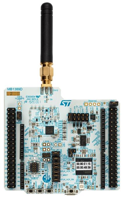
개요
NUCLEO-WL55JC는 STM32WL series의 성능·전력·기능 조합을 시험하는 Nucleo-64 LPWAN prototype board입니다.
- UFBGA73 multiprotocol STM32WL55JC
- 48MHz Cortex-M4/M0+ dual core
- 150~960MHz LoRa·(G)FSK·(G)MSK·BPSK RF transceiver
- Flash 256KB, SRAM 64KB
- User LED 3개, user button 3개, reset button 1개
- 32.768kHz LSE crystal과 32MHz HSE oscillator
- Micro-B USB, MIPI debug, Arduino Uno V3, 모든 I/O용 ST morpho connector
- SMA antenna 포함
- ST-LINK·USB VBUS·external source 전원과 USB mass-storage·Virtual COM·debug 기능의 STLINK-V3
- STM32CubeWL library·example 및 IAR Embedded Workbench·MDK-ARM·STM32CubeIDE 지원
- LoRaWAN·Sigfox·wM-Bus 등 end-node rapid prototyping에 적합한 fully-open hardware
Hardware
STM32WL55JC는 long-range LPWAN radio와 ultra-low-power dual core를 통합합니다.
- Radio
- 150~960MHz
- LoRa·(G)FSK·(G)MSK·BPSK
- RX sensitivity: 1.2Kbit/s 2-FSK -123dBm, 10.4kHz SF12 LoRa -148dBm
- high-power transmitter 최대 +22dBm, low-power transmitter 최대 +15dBm
- ETSI EN 300 220/300 113/301 166, FCC CFR47 Part 15/24/90/101, ARIB STD-T30/T-67/T-108
- LoRaWAN·Sigfox·W-MBus·proprietary protocol
- Core
- Cortex-M4: ART 0-wait-state flash, 최대 48MHz, MPU·DSP, 1.25DMIPS/MHz
- Cortex-M0+: 최대 48MHz, MPU, 0.95DMIPS/MHz
- Security·identification
- AES-256
- true RNG
- PCROP·RDP·WRP sector protection
- CRC
- IEEE 802-2001 compliant 64-bit device ID와 96-bit die ID
- hardware PKA와 key management
- secure sub-GHz MAC
- SFU·SFI
- Supply·reset
- high-efficiency embedded SMPS
- SMPS-to-LDO smart switch
- 5-threshold ultra-safe low-power BOR
- ultra-low-power POR/PDR
- programmable voltage detector
- RTC·20×32-bit backup register VBAT mode
- Clock
- 32MHz crystal과 programmable-supply TCXO
- calibration 가능한 RTC 32kHz oscillator
- factory-trimmed 16MHz HSI ±1%
- low-power 32kHz RC
- 100kHz~48MHz multi-speed low-power RC
- CPU·ADC·audio PLL
- Memory
- Flash 256KB, RAM 64KB, 20×32-bit backup register
- USART·SPI bootloader
- OTA firmware update
- sector R/W protection
- Analog
- 2.5MSPS 12-bit ADC, oversampling으로 최대 16-bit, 3.6V range
- low-power sample-and-hold 12-bit DAC
- ultra-low-power comparator 2개
- Cortex-M4와 M0+ firmware 통신용 mailbox·semaphore
- Controller
- ADC·DAC·SPI·I2C·LPUART·USART·AES·timer용 각 7-channel DMA 2개
- USART 2개, LPUART 1개
- 16Mbit/s SPI 2개 중 하나는 I2S 지원
- SMBus/PMBus I2C 3개
- 16-bit 1-channel timer 2개, motor-control 16-bit 4-channel 1개, 32-bit 4-channel 1개
- ultra-low-power 16-bit timer 3개
- 32-bit sub-second wakeup RTC
- SysTick·independent watchdog·window watchdog 각 1개
- 대부분 5V tolerant인 I/O 최대 43개
- SWD·JTAG와 dual-CPU cross-trigger development support
Zephyr 지원 기능
| Interface | Controller | Driver/Component |
|---|---|---|
| AES | on-chip | crypto |
| CLOCK | on-chip | reset and clock_control |
| FLASH | on-chip | flash |
| GPIO | on-chip | gpio |
| I2C | on-chip | i2c |
| MPU | on-chip | arch/arm |
| NVIC | on-chip | arch/arm |
| PINMUX | on-chip | pinmux |
| RADIO | on-chip | LoRa |
| RNG | on-chip | entropy |
| SPI | on-chip | spi |
| UART | on-chip | serial port-polling; serial port-interrupt |
| ADC | on-chip | ADC Controller |
| DAC | on-chip | DAC Controller |
| die-temp | on-chip | die temperature sensor |
| RTC | on-chip | rtc |
표 밖 기능은 아직 지원하지 않습니다. 기본 설정은 boards/st/nucleo_wl55jc/nucleo_wl55jc_defconfig와 boards/st/nucleo_wl55jc/nucleo_wl55jc.dts입니다.
Connection과 I/O
GPIO controller 4개가 pin muxing, input/output, pull-up 등을 담당합니다.
기본 Zephyr peripheral mapping
LPUART_1 TX/RX : PA3/PA2 (ST-Link Virtual Port Com)I2C_2_SCL : PA12 (Arduino I2C)I2C_2_SDA : PA11 (Arduino I2C)SPI_1_NSS : PA4 (arduino_spi)SPI_1_SCK : PA5 (arduino_spi)SPI_1_MISO : PA6 (arduino_spi)SPI_1_MOSI : PA7 (arduino_spi)ADC1_IN5 : PB1 (Arduino pin A0)DAC1_OUT1 : PA10 (Arduino pin A2)
Clock과 serial
기본 system clock은 32MHz HSE입니다. (LP)U(S)ART 2개 중 console은 LPUART_1, 115200 8N1입니다.
Programming and debugging
STLINK-V3는 Zephyr SDK v0.11.0부터 포함된 OpenOCD가 지원하며 stm32cubeprogrammer runner도 선택할 수 있습니다.
$ minicom -D /dev/ttyUSB0west build -b nucleo_wl55jc samples/hello_world
west flashHello World! armStock firmware 주의: 출고 firmware는 sleep mode를 시연합니다. Debug-compatible 기본 OpenOCD configuration은 SoC가 sleep 중일 때 flash할 수 없으므로, 출고 firmware 위에 처음 flash할 때 board의 openocd.cfg를 sleep-compatible configuration으로 바꿔야 합니다.
Debugging
west build -b nucleo_wl55jc samples/basic/blinky
west debug
참고 자료
Source
출처
영어 원문에는 문단, 문서 지시문, 표, 코드, 코드 심벌, 경로를 그대로 보존했습니다.