Part 1
요약·해설
지원표 26행과 중복 RTC, 11개 peripheral mapping, CPU core 표기 불일치, J-Link OB runner를 설명합니다.
MCU
STM32F722ZE
CPU
Cortex-M7
Clock max
216MHz
Support
26 rows
Part 2
접을 수 있는 영어 원문 전체
영어 원문 전체 펼치기
원문 SHA-256
44C1BB80A040DD8F892A26EEFFE24F6154AD2DC861262B29232E3274C2C57C86
.. _nucleo_f722ze_board:

ST Nucleo F722ZE
################

Overview
********

The Nucleo F722ZE board features an ARM Cortex-M7 based STM32F722ZE MCU.

Key Features:

- STM32 microcontroller in LQFP144 package
- USB full-speed/high-speed device
- 3 user LEDs
- 1 user button and 1 reset button
- 32.768 kHz crystal oscillator
- Board connectors:
   - USB Micro-AB
   - SWD
   - ST Zio connector (Arduino Uno R3 compatible)
   - ST Morpho connector
- On-board ST-LINK debugger/programmer
- Flexible power supply options, including ST-LINK VBUS and external sources.

.. image:: ../../../../../../../boards/st/nucleo_f722ze/doc/img/nucleo_f722ze.jpg
   :width: 800px
   :align: center
   :alt: Nucleo F722ZE

Hardware
********

Nucleo F722ZE provides the following hardware components:

- STM32F722ZET6 microcontroller in LQFP144 package
- ARM |reg| Cortex |reg|-M4 with FPU
- Adaptive Real-Time Accelerator (ART Accelerator)
- 216MHz max CPU frequency
- 512 KB flash
- 256 KB RAM
- I2C (3)
- USART/UART (4)
- SPI (5)
- I2S (3)
- SAI (2)
- USB OTG Full-speed (1)
- USB OTG Full-speed/high-speed (1)
- SDMMC (2)
- CAN (1)
- Dual mode Quad-SPI
- Random number generator (RNG)
- 3x 12-bit ADC, up to 2.4 MSPS with 24 channels or 7.2 MSPS in triple-interleaved mode
- 2x 12-bit DAC
- 16-channel DMA controller
- 16-bit timers (13) with PWM, pulse counter, and quadrature features
- 32-bit timers (2) with PWM, pulse counter, and quadrature features
- CRC
- 96-bit unique ID
- Die temperature

Supported Features
==================

+---------------+------------+-------------------------------+
| Interface     | Controller | Driver/Component              |
+===============+============+===============================+
| NVIC          | on-chip    | arch/arm                      |
+---------------+------------+-------------------------------+
| MPU           | on-chip    | arch/arm                      |
+---------------+------------+-------------------------------+
| ADC           | on-chip    | adc                           |
+---------------+------------+-------------------------------+
| CAN           | on-chip    | can                           |
+---------------+------------+-------------------------------+
| USART/UART    | on-chip    | console, serial               |
+---------------+------------+-------------------------------+
| TIMER         | on-chip    | counter, pwm, timer           |
+---------------+------------+-------------------------------+
| DAC           | on-chip    | dac                           |
+---------------+------------+-------------------------------+
| DMA           | on-chip    | dma                           |
+---------------+------------+-------------------------------+
| GPIO          | on-chip    | gpio                          |
+---------------+------------+-------------------------------+
| HWINFO        | on-chip    | hwinfo                        |
+---------------+------------+-------------------------------+
| I2C           | on-chip    | i2c                           |
+---------------+------------+-------------------------------+
| EXTI          | on-chip    | interrupt_controller          |
+---------------+------------+-------------------------------+
| BACKUP_SRAM   | on-chip    | memory                        |
+---------------+------------+-------------------------------+
| QUADSPI       | on-chip    | memory                        |
+---------------+------------+-------------------------------+
| PINMUX        | on-chip    | pinctrl                       |
+---------------+------------+-------------------------------+
| RCC           | on-chip    | reset                         |
+---------------+------------+-------------------------------+
| RTC           | on-chip    | rtc                           |
+---------------+------------+-------------------------------+
| DIE_TEMP      | on-chip    | sensor                        |
+---------------+------------+-------------------------------+
| VREF          | on-chip    | sensor                        |
+---------------+------------+-------------------------------+
| VBAT          | on-chip    | sensor                        |
+---------------+------------+-------------------------------+
| SPI           | on-chip    | spi                           |
+---------------+------------+-------------------------------+
| USBOTG_HS     | on-chip    | usb                           |
+---------------+------------+-------------------------------+
| USBOTG_FS     | on-chip    | usb                           |
+---------------+------------+-------------------------------+
| IWDG          | on-chip    | watchdog                      |
+---------------+------------+-------------------------------+
| WWDG          | on-chip    | watchdog                      |
+---------------+------------+-------------------------------+
| RTC           | on-chip    | rtc                           |
+---------------+------------+-------------------------------+

Connections and IOs
===================

- SDMMC1: Pins marked as "SDMMC" on the ST Zio connector.
   - D0: PC8 (CN8 pin 2)
   - D1: PC9 (CN8 pin 4)
   - D2: PC10 (CN8 pin 6)
   - D3: PC11 (CN8 pin 8)
   - CK: PC12 (CN8 pin 10)
   - CMD: PD2 (CN8 pin 12)
- ADC1:
   - IN3: PA3 (CN9 pin 1, Arduino A0)
   - IN10: PC0 (CN9 pin 3, Arduino A1)
- DAC1:
   - OUT1: PA4 (CN7 pin 17)
- I2C2: Pins marked as "I2C" on the ST Zio connector.
   - SCL: PF1 (CN9 pin 19)
   - SDA: PF0 (CN9 pin 21)
- CAN1: Pins marked as "CAN" on the ST Zio connector.
   - RX: PD0 (CN9 pin 25)
   - TX: PD1 (CN9 pin 27)
- USART2: Pins marked as "USART" on the ST Zio connector.
   - RX: PD6 (CN9 pin 4)
   - TX: PD5 (CN9 pin 6)
   - RTS: PD4 (CN9 pin 8)
   - CTS: PD3 (CN9 pin 10)
- PWM1: Uses TIMER1.
   - PE13 (CN10 pin 10, Arduino D3)
   - PE11 (CN10 pin 6, Arduino D5)
- USART3: Connected to ST-Link virtual COM port.
   - TX: PD8
   - RX: PD9
- USART6: Arduino UART port.
   - RX: PG9 (CN10 pin 16, Arduino D0)
   - TX: PG14 (CN10 pin 14, Arduino D1)
- USBOTG_FS: Connected to USB Micro-AB connector (CN13)
   - DM: PA11
   - DP: PA12
   - ID: PA10
- QUADSPI: Pins marked as "QSPI" on the ST Zio connector.
   - CS: PB6 (CN10 pin 13)
   - CLK: PB2 (CN10 pin 15)
   - IO3: PD13 (CN10 pin 19)
   - IO1: PD12 (CN10 pin 21)
   - IO0: PD11 (CN10 pin 23)
   - IO2: PE2 (CN10 pin 25)

System Clock
------------

By default, the system clock is driven by the external clock supplied by
the ST-LINK interface. Nucleo F722ZE system clock can be driven by internal
or external sources.

Serial Port
-----------

Zephyr console is assigned to UART3 (ST-Link Virtual COM Port) by default,
using 115200 8N1.

Programming and Debugging
*************************

The ``nucleo_f722ze`` can be flashed and debugged in the typical manner.
The Nucleo F722ZE board includes an ST-LINK V2-1 debugger, which can be used
with the OpenOCD version provided with the Zephyr SDK. Refer to
:ref:`build_an_application` and :ref:`application_run` for detailed
instructions.

Flashing
========

Build the :ref:`hello_world` application and flash it using the on-board
ST-LINK interface:

.. zephyr-app-commands::
   :zephyr-app: samples/hello_world
   :board: nucleo_f722ze
   :goals: build flash

Debugging
=========

.. zephyr-app-commands::
   :zephyr-app: samples/hello_world
   :board: nucleo_f722ze
   :maybe-skip-config:
   :goals: debug

J-Link OB Firmware
------------------

Like many other STM32 evaluation boards, the Nucleo F722ZE's on-board ST-LINK
debug interface may be flashed with `SEGGER J-Link OB firmware`_. This
firmware turns the ST-LINK into a J-Link probe. If the on-board debugger has
been re-flashed with J-Link OB firmware, simply append ``--runner jlink`` to
all flashing/debugging commands.

References
**********

More information about the STM32F722ZE:

- `STM32F722ZE on www.st.com`_
- `STM32F722ZE Reference Manual (RM0431)`_ (PDF)

More information about Nucleo F722ZE:

- `Nucleo F722ZE on www.st.com`_
- `STM32 Nucleo-144 User Manual (UM1974)`_ (PDF)

.. _SEGGER J-Link OB firmware:
   https://www.segger.com/products/debug-probes/j-link/models/other-j-links/st-link-on-board/

.. _STM32F722ZE on www.st.com:
   https://www.st.com/en/microcontrollers-microprocessors/stm32f722ze.html

.. _STM32F722ZE Reference Manual (RM0431):
   https://www.st.com/resource/en/reference_manual/rm0431-stm32f72xxx-and-stm32f73xxx-advanced-armbased-32bit-mcus-stmicroelectronics.pdf

.. _Nucleo F722ZE on www.st.com:
   https://www.st.com/en/evaluation-tools/nucleo-f722ze.html

.. _STM32 Nucleo-144 User Manual (UM1974):
   https://www.st.com/resource/en/user_manual/um1974-stm32-nucleo144-boards-mb1137-stmicroelectronics.pdf
Part 3
한국어 전문 번역
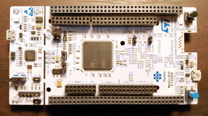
개요
Nucleo F722ZE는 Arm Cortex-M7 기반 STM32F722ZE board입니다. LQFP144 MCU, USB FS/HS device, user LED 3개, USER·RESET button, 32.768kHz crystal, Micro-AB USB·SWD·ST Zio·ST Morpho connector, onboard ST-LINK와 flexible power를 제공합니다.
Hardware
- LQFP144 STM32F722ZET6
- 공식 Hardware 목록에는 ‘Cortex-M4 with FPU’라고 기재
- ART Accelerator, 최대 216MHz
- 512KB flash, 256KB RAM
- I2C 3개, USART/UART 4개, SPI 5개, I2S 3개, SAI 2개
- USB OTG FS 1개, USB OTG FS/HS 1개, SDMMC 2개, CAN 1개
- Dual-mode Quad-SPI, RNG
- 24-channel 12-bit ADC 3개: 2.4MSPS 또는 triple-interleaved 7.2MSPS
- 12-bit DAC 2개, 16-channel DMA
- 16-bit timer 13개와 32-bit timer 2개
- CRC, 96-bit unique ID, die temperature
Zephyr 지원 기능
| Interface | Controller | Driver/Component |
|---|---|---|
| NVIC | on-chip | arch/arm |
| MPU | on-chip | arch/arm |
| ADC | on-chip | adc |
| CAN | on-chip | can |
| USART/UART | on-chip | console, serial |
| TIMER | on-chip | counter, pwm, timer |
| DAC | on-chip | dac |
| DMA | on-chip | dma |
| GPIO | on-chip | gpio |
| HWINFO | on-chip | hwinfo |
| I2C | on-chip | i2c |
| EXTI | on-chip | interrupt_controller |
| BACKUP_SRAM | on-chip | memory |
| QUADSPI | on-chip | memory |
| PINMUX | on-chip | pinctrl |
| RCC | on-chip | reset |
| RTC | on-chip | rtc |
| DIE_TEMP | on-chip | sensor |
| VREF | on-chip | sensor |
| VBAT | on-chip | sensor |
| SPI | on-chip | spi |
| USBOTG_HS | on-chip | usb |
| USBOTG_FS | on-chip | usb |
| IWDG | on-chip | watchdog |
| WWDG | on-chip | watchdog |
| RTC | on-chip | rtc |
Connection과 I/O
- SDMMC1 D0/D1/D2/D3/CK/CMD: PC8/PC9/PC10/PC11/PC12/PD2 (CN8 2/4/6/8/10/12)
- ADC1 IN3 PA3(CN9-1, A0), IN10 PC0(CN9-3, A1)
- DAC1 OUT1 PA4(CN7-17)
- I2C2 SCL PF1(CN9-19), SDA PF0(CN9-21)
- CAN1 RX PD0(CN9-25), TX PD1(CN9-27)
- USART2 RX/TX/RTS/CTS PD6/PD5/PD4/PD3 (CN9 4/6/8/10)
- PWM1/TIMER1 PE13(CN10-10,D3), PE11(CN10-6,D5)
- USART3 VCOM TX/RX PD8/PD9
- USART6 Arduino UART RX PG9(D0), TX PG14(D1)
- USBOTG_FS CN13 DM PA11, DP PA12, ID PA10
- QUADSPI CS PB6, CLK PB2, IO3 PD13, IO1 PD12, IO0 PD11, IO2 PE2 (CN10 13/15/19/21/23/25)
Clock과 console
기본 system clock은 ST-LINK interface가 공급하는 external clock으로 구동되며 internal/external source를 선택할 수 있습니다. Zephyr console은 UART3 VCOM, 115200 8N1입니다.
Programming and debugging
west build -b nucleo_f722ze samples/hello_world
west flash
west build -b nucleo_f722ze samples/hello_world
west debugJ-Link OB firmware
Onboard ST-LINK를 SEGGER J-Link OB firmware로 바꿨다면 모든 flash/debug command에 --runner jlink를 추가합니다.
참고 자료
Source
출처
영어 원문에는 문단, 문서 지시문, 표, 코드, 코드 심벌, 경로를 그대로 보존했습니다.