Part 1
요약·해설
13개 Zephyr peripheral mapping과 기본 UART/I2C/SPI pin, SWD와 UF2 두 programming 경로를 보존합니다.
2× Cortex-M0+
133MHz
16MB XIP
UF2
Part 2
접을 수 있는 영어 원문 전체
영어 원문 전체 펼치기
6F4094269615984C07CB2BF9E27CAAB3D335E0ED860377E3B93D2B2E04CDEDE9
.. _sparkfun_pro_micro_rp2040:

SparkFun Pro Micro RP2040
#########################

Overview
********

The SparkFun Pro Micro RP2040 is a small, low-cost, versatile board from
SparkFun. It is equipped with an RP2040 SoC, an on-board WS2812 addressable
LED, a USB connector, and a Qwiic connector. The USB bootloader allows it
to be flashed without any adapter, in a drag-and-drop manner.

Hardware
********
- Dual core Arm Cortex-M0+ processor running up to 133MHz
- 264KB on-chip SRAM
- 16MB on-board QSPI flash with XIP capabilities
- 18 GPIO pins
- 4 Analog inputs
- 1 UART peripherals
- 1 SPI controllers
- 2 I2C controllers (one via Qwiic connector)
- 16 PWM channels
- USB 1.1 controller (host/device)
- 8 Programmable I/O (PIO) for custom peripherals
- On-board RGB LED
- 1 Watchdog timer peripheral


.. figure:: ../../../../../../../boards/sparkfun/pro_micro_rp2040/doc/img/sparkfun_pro_micro_rp2040.jpg
     :align: center
     :alt: SparkFun Pro Micro RP2040

     SparkFun Pro Micro RP2040 (Image courtesy of SparkFun)

Supported Features
==================

The sparkfun_pro_micro_rp2040 board configuration supports the following
hardware features:

.. list-table::
   :header-rows: 1

   * - Peripheral
     - Kconfig option
     - Devicetree compatible
   * - NVIC
     - N/A
     - :dtcompatible:`arm,v6m-nvic`
   * - UART
     - :kconfig:option:`CONFIG_SERIAL`
     - :dtcompatible:`raspberrypi,pico-uart`
   * - GPIO
     - :kconfig:option:`CONFIG_GPIO`
     - :dtcompatible:`raspberrypi,pico-gpio`
   * - ADC
     - :kconfig:option:`CONFIG_ADC`
     - :dtcompatible:`raspberrypi,pico-adc`
   * - I2C
     - :kconfig:option:`CONFIG_I2C`
     - :dtcompatible:`snps,designware-i2c`
   * - SPI
     - :kconfig:option:`CONFIG_SPI`
     - :dtcompatible:`raspberrypi,pico-spi`
   * - USB Device
     - :kconfig:option:`CONFIG_USB_DEVICE_STACK`
     - :dtcompatible:`raspberrypi,pico-usbd`
   * - HWINFO
     - :kconfig:option:`CONFIG_HWINFO`
     - N/A
   * - Watchdog Timer (WDT)
     - :kconfig:option:`CONFIG_WATCHDOG`
     - :dtcompatible:`raspberrypi,pico-watchdog`
   * - PWM
     - :kconfig:option:`CONFIG_PWM`
     - :dtcompatible:`raspberrypi,pico-pwm`
   * - Flash
     - :kconfig:option:`CONFIG_FLASH`
     - :dtcompatible:`raspberrypi,pico-flash`
   * - Clock controller
     - :kconfig:option:`CONFIG_CLOCK_CONTROL`
     - :dtcompatible:`raspberrypi,pico-clock-controller`
   * - UART (PIO)
     - :kconfig:option:`CONFIG_SERIAL`
     - :dtcompatible:`raspberrypi,pico-uart-pio`

Pin Mapping
===========

The peripherals of the RP2040 SoC can be routed to various pins on the board.
The configuration of these routes can be modified through DTS. Please refer to
the datasheet to see the possible routings for each peripheral.

Default Zephyr Peripheral Mapping:
----------------------------------

.. rst-class:: rst-columns

- UART0_TX : P0
- UART0_RX : P1
- I2C1_SDA : P2
- I2C1_SCL : P3
- SPI0_RX : P20
- SPI0_SCK : P18
- SPI0_TX : P19

Programming and Debugging
*************************

Flashing
========

Using UF2
---------

The Pro Micro board does make the SWD pins available on pads on the
underside of the board. You can solder to these pins, and use a JTag
debugger. You can also flash the SparkFun ProMicro RP2040 with a UF2 file.
By default, building an app for this board will generate a
`build/zephyr/zephyr.uf2` file. If the Pro Micro RP2040 is powered on with
the `BOOTSEL` button pressed, it will appear on the host as a mass storage
device. The UF2 file should be copied to the device, which will
flash the Pro Micro RP2040.

.. target-notes::

.. _Getting Started with Raspberry Pi Pico:
  https://datasheets.raspberrypi.com/pico/getting-started-with-pico.pdf

.. _Graphical Datasheet:
  https://cdn.sparkfun.com/assets/e/2/7/6/b/ProMicroRP2040_Graphical_Datasheet.pdf
Part 3
한국어 전문 번역
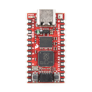
개요
SparkFun Pro Micro RP2040은 작고 저렴하며 다양한 용도로 쓸 수 있는 board입니다. RP2040 SoC, onboard WS2812 addressable LED, USB connector, Qwiic connector를 갖추며 USB bootloader 덕분에 adapter 없이 drag-and-drop 방식으로 flash할 수 있습니다.
Hardware
- 최대 133MHz dual-core Arm Cortex-M0+ processor
- On-chip SRAM 264KB
- XIP가 가능한 onboard QSPI flash 16MB
- GPIO pin 18개
- Analog input 4개
- UART peripheral 1개
- SPI controller 1개
- I2C controller 2개(Qwiic connector 경유 1개 포함)
- PWM channel 16개
- USB 1.1 host/device controller
- Custom peripheral용 Programmable I/O(PIO) 8개
- Onboard RGB LED
- Watchdog timer peripheral 1개
지원 기능
| Peripheral | Kconfig option | Devicetree compatible |
|---|---|---|
| NVIC | N/A | arm,v6m-nvic |
| UART | CONFIG_SERIAL | raspberrypi,pico-uart |
| GPIO | CONFIG_GPIO | raspberrypi,pico-gpio |
| ADC | CONFIG_ADC | raspberrypi,pico-adc |
| I2C | CONFIG_I2C | snps,designware-i2c |
| SPI | CONFIG_SPI | raspberrypi,pico-spi |
| USB Device | CONFIG_USB_DEVICE_STACK | raspberrypi,pico-usbd |
| HWINFO | CONFIG_HWINFO | N/A |
| Watchdog Timer (WDT) | CONFIG_WATCHDOG | raspberrypi,pico-watchdog |
| PWM | CONFIG_PWM | raspberrypi,pico-pwm |
| Flash | CONFIG_FLASH | raspberrypi,pico-flash |
| Clock controller | CONFIG_CLOCK_CONTROL | raspberrypi,pico-clock-controller |
| UART (PIO) | CONFIG_SERIAL | raspberrypi,pico-uart-pio |
Pin mapping
RP2040 peripheral은 board의 여러 pin으로 route할 수 있으며 DTS에서 경로를 바꿀 수 있습니다. Peripheral별 가능한 route는 datasheet를 확인합니다. Zephyr 기본 mapping은 다음과 같습니다.
UART0_TX : P0UART0_RX : P1I2C1_SDA : P2I2C1_SCL : P3SPI0_RX : P20SPI0_SCK : P18SPI0_TX : P19
Programming and debugging
UF2 flashing
Board underside pad에 SWD pin이 노출되어 있어 납땜 후 JTAG debugger를 사용할 수 있습니다. Adapter 없이 UF2 file로도 flash할 수 있습니다. 이 board target을 build하면 기본적으로 build/zephyr/zephyr.uf2가 생성됩니다.
BOOTSEL button을 누른 상태로 Pro Micro RP2040의 전원을 켜면 host에 mass-storage device로 나타납니다. 생성된 UF2 file을 그 device로 복사하면 board가 flash됩니다.
참고 자료
Source
출처
영어 원문에는 문단, 문서 지시문, 표, 코드, 코드 심벌, 경로를 그대로 보존했습니다.