Part 1
요약·해설
Board target과 공식 defconfig 경로의 이름 차이를 보존하면서 지원 기능·pin·flash를 설명합니다.
EFR32FG13P
2.4GHz · 915MHz
19dBm
slwrb4255
Part 2
접을 수 있는 영어 원문 전체
영어 원문 전체 펼치기
6B7C4B04E9DBE2EFE21946C33DD1B1493E8810944D272092C2570683D681F2BF
.. _slwrb4255a:

EFR32FG13 2400/915 MHz 19 dBm Dual Band (SLWRB4255A)
####################################################

Overview
********

The EFR32FG13P Flex Gecko 2.4 GHz and 915 MHz Radio Board is delivered as a
`standalone Proprietary Wireless radio board`_. It contains a EFR32FG13P Wireless
SoC built on an ARM Cortex®-M4F processor with excellent low power capabilities.

.. figure:: ../../../../../../../../boards/silabs/radio_boards/slwrb4255a/doc/efr32fg13-slwrb4255a.jpg
   :align: center
   :alt: SLWRB4255A Flex Gecko 2.4 GHz and 915 MHz Radio Board

   SLWRB4255A (image courtesy of Silicon Labs)

The BRD4255A a.k.a. SLWRB4255A radio board plugs into the Wireless Starter Kit
Mainboard BRD4001A and is supported as one of :ref:`silabs_radio_boards`.

Hardware
********

- EFR32FG13P233F512GM48 Flex Gecko SoC
- CPU core: ARM Cortex®-M4 with FPU
- Flash memory: 512 kB
- RAM: 64 kB
- Transmit power: up to 19 dBm
- Operation frequency: 2.4 GHz, 915 MHz
- Crystals for LFXO (32.768 kHz) and HFXO (38.4 MHz).

For more information about the EFR32FG13 SoC and BRD4255A board, refer to these
documents:

- `EFR32FG13 Website`_
- `EFR32FG13 Datasheet`_
- `EFR32xG13 Reference Manual`_
- `BRD4255A Reference Manual`_

Supported Features
==================

The board configuration supports the following hardware features:

+-----------+------------+-------------------------------------+
| Interface | Controller | Driver/Component                    |
+===========+============+=====================================+
| MPU       | on-chip    | memory protection unit              |
+-----------+------------+-------------------------------------+
| NVIC      | on-chip    | nested vector interrupt controller  |
+-----------+------------+-------------------------------------+
| SYSTICK   | on-chip    | systick                             |
+-----------+------------+-------------------------------------+
| COUNTER   | on-chip    | rtcc                                |
+-----------+------------+-------------------------------------+
| FLASH     | on-chip    | flash memory                        |
+-----------+------------+-------------------------------------+
| GPIO      | on-chip    | gpio                                |
+-----------+------------+-------------------------------------+
| UART      | on-chip    | serial port-polling;                |
|           |            | serial port-interrupt               |
+-----------+------------+-------------------------------------+
| SPI(M)    | on-chip    | spi port-polling                    |
+-----------+------------+-------------------------------------+
| WATCHDOG  | on-chip    | watchdog                            |
+-----------+------------+-------------------------------------+

The default configuration can be found in
:zephyr_file:`boards/silabs/radio_boards/slwrb4255/slwrb4255_defconfig`

Connections and IOs
===================

In the following table, the column **Pin** contains Pin names. For example, PA2
means Pin number 2 on PORTA, as used in the board's datasheets and manuals.

+-------+-------------+-------------------------------------+
| Pin   | Function    | Usage                               |
+=======+=============+=====================================+
| PF4   | GPIO        | LED0                                |
+-------+-------------+-------------------------------------+
| PF5   | GPIO        | LED1                                |
+-------+-------------+-------------------------------------+
| PF6   | GPIO        | Push Button PB0                     |
+-------+-------------+-------------------------------------+
| PF7   | GPIO        | Push Button PB1                     |
+-------+-------------+-------------------------------------+
| PA5   | GPIO        | Board Controller Enable VCOM_ENABLE |
+-------+-------------+-------------------------------------+
| PA0   | USART0_TX   | UART Console VCOM_TX US0_TX #0      |
+-------+-------------+-------------------------------------+
| PA1   | USART0_RX   | UART Console VCOM_RX US0_RX #0      |
+-------+-------------+-------------------------------------+
| PC6   | SPI_MOSI    | Flash MOSI US1_TX #11               |
+-------+-------------+-------------------------------------+
| PC7   | SPI_MISO    | Flash MISO US1_RX #11               |
+-------+-------------+-------------------------------------+
| PC8   | SPI_SCLK    | Flash SCLK US1_CLK #11              |
+-------+-------------+-------------------------------------+
| PA4   | SPI_CS      | Flash Chip Select (GPIO)            |
+-------+-------------+-------------------------------------+

System Clock
============

The EFR32FG13P SoC is configured to use the 38.4 MHz external oscillator on the
board.

Serial Port
===========

The EFR32FG13P SoC has three USARTs and one Low Energy UARTs (LEUART).
USART0 is connected to the board controller and is used for the console.

Programming and Debugging
*************************

Flashing
========

Connect the BRD4001A board with a mounted BRD4255A radio module to your host
computer using the USB port.

Here is an example for the :ref:`hello_world` application.

.. zephyr-app-commands::
   :zephyr-app: samples/hello_world
   :board: slwrb4255a
   :goals: flash

Open a serial terminal (minicom, putty, etc.) with the following settings:

- Speed: 115200
- Data: 8 bits
- Parity: None
- Stop bits: 1

Reset the board and you should see the following message in the terminal:

.. code-block:: console

   Hello World! slwrb4255a


.. _EFR32FG13 Website:
   https://www.silabs.com/wireless/proprietary/efr32fg13-series-1-sub-ghz-2-4-ghz-socs

.. _EFR32FG13 Datasheet:
   https://www.silabs.com/documents/public/data-sheets/efr32fg13-datasheet.pdf

.. _EFR32xG13 Reference Manual:
   https://www.silabs.com/documents/public/reference-manuals/efr32xg13-rm.pdf

.. _standalone Proprietary Wireless radio board:
   https://www.silabs.com/development-tools/wireless/proprietary/slwrb4255a-efr32fg13-915-mhz-radio-board

.. _BRD4255A Reference Manual:
   https://www.silabs.com/documents/public/reference-manuals/brd4255a-rm.pdf
Part 3
한국어 전문 번역
개요
EFR32FG13P Flex Gecko 2.4GHz·915MHz Radio Board는 standalone Proprietary Wireless radio board로 제공됩니다. 저전력 특성이 뛰어난 ARM Cortex-M4F 기반 EFR32FG13P Wireless SoC를 탑재합니다.
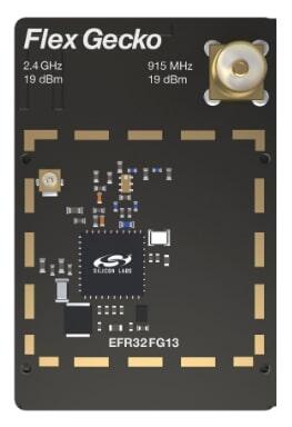
BRD4255A(SLWRB4255A) radio board는 Wireless Starter Kit Mainboard BRD4001A에 장착하며 Zephyr의 Silicon Labs radio board 중 하나로 지원됩니다.
하드웨어
- EFR32FG13P233F512GM48 Flex Gecko SoC
- FPU가 있는 ARM Cortex-M4 CPU core
- Flash 512kB, RAM 64kB
- 최대 19dBm transmit power
- 2.4GHz와 915MHz 동작
- LFXO 32.768kHz와 HFXO 38.4MHz crystal
상세 자료:
- EFR32FG13 웹사이트
- EFR32FG13 Datasheet
- EFR32xG13 Reference Manual
- Standalone radio board
- BRD4255A Reference Manual
지원 기능
Board configuration은 다음 hardware 기능을 지원합니다.
| Interface | Controller | Driver/Component |
|---|---|---|
| MPU | on-chip | memory protection unit |
| NVIC | on-chip | nested vector interrupt controller |
| SYSTICK | on-chip | systick |
| COUNTER | on-chip | rtcc |
| FLASH | on-chip | flash memory |
| GPIO | on-chip | gpio |
| UART | on-chip | serial port-polling; serial port-interrupt |
| SPI(M) | on-chip | spi port-polling |
| WATCHDOG | on-chip | watchdog |
기본 설정은 boards/silabs/radio_boards/slwrb4255/slwrb4255_defconfig에 있습니다.
연결과 I/O
표의 Pin은 pin 이름입니다. 예를 들어 PA2는 board datasheet와 manual에서 사용하는 PORTA의 2번 pin을 뜻합니다.
| Pin | Function | Usage |
|---|---|---|
| PF4 | GPIO | LED0 |
| PF5 | GPIO | LED1 |
| PF6 | GPIO | Push Button PB0 |
| PF7 | GPIO | Push Button PB1 |
| PA5 | GPIO | Board Controller Enable VCOM_ENABLE |
| PA0 | USART0_TX | UART Console VCOM_TX US0_TX #0 |
| PA1 | USART0_RX | UART Console VCOM_RX US0_RX #0 |
| PC6 | SPI_MOSI | Flash MOSI US1_TX #11 |
| PC7 | SPI_MISO | Flash MISO US1_RX #11 |
| PC8 | SPI_SCLK | Flash SCLK US1_CLK #11 |
| PA4 | SPI_CS | Flash Chip Select (GPIO) |
System clock
SoC는 board의 38.4MHz external oscillator를 사용하도록 구성됩니다.
Serial port
EFR32FG13P SoC에는 USART 3개와 Low Energy UART(LEUART) 1개가 있습니다. USART0는 board controller에 연결되어 console로 사용됩니다.
Programming and debugging
Flashing
BRD4001A에 BRD4255A(SLWRB4255A) radio module을 장착하고 USB port로 host computer에 연결합니다. hello_world application을 build하고 flash합니다.
west build -b slwrb4255a samples/hello_world
west flash
Serial terminal은 115200 baud, data 8 bit, parity 없음, stop bit 1로 설정합니다. Reset 후 다음 메시지가 표시됩니다.
Hello World! slwrb4255aSource
출처
영어 원문에는 문단, 문서 지시문, 표, 코드, 코드 심벌, 경로를 그대로 보존했습니다.