Part 1
요약·해설
일반 prototype용이 아닌 trace 전용 성격, 20-pin JTAG/SWD/TRACE mapping, 168 MHz clock과 J-Trace/J-Link 흐름을 설명합니다.
STM32F407VE · Cortex-M4
Hardware trace reference
20-pin JTAG/SWD/TRACE
J-Trace · J-Link
Part 2
접을 수 있는 영어 원문 전체
영어 원문 전체 펼치기
68AAAAFD78BA8634FAD1DD9860B129A321C981A2F87C570C993A563CB0A51FD9
.. _segger_trb_stm32f407:

Cortex-M Trace Reference Board V1.2
###################################

Overview
********

The Cortex-M Trace Reference Board V1.2 (SEGGER-TRB-STM32F407 for short)
board is a reference board, based on the ST Microelectronics STM32F407VE
ARM Cortex-M4 CPU, to test hardware tracing with the SEGGER Trace-Pro
debuggers. It is not meant for general prototype development because
it is extremely limited when it comes to IO, and only has 3 LEDs.

.. figure:: ../../../../../../../boards/segger/trb_stm32f407/doc/img/segger_trb_stm32f407.jpg
     :align: center
     :alt: SEGGER-TRB-STM32F407

     SEGGER-TRB-STM32F407

Hardware
********

Information about the board can be found at the `SEGGER website`_ .
The `ST STM32F407VE website`_ contains the processor's information
and the datasheet.

Supported Features
==================

The SEGGER-TRB-STM32F407 board configuration supports the following
hardware features:

+------------+------------+------------------------------+
| Interface  | Controller | Driver/Component             |
+============+============+==============================+
| NVIC       | on-chip    | nested vectored              |
|            |            | interrupt controller         |
+------------+------------+------------------------------+
| SYSTICK    | on-chip    | system clock                 |
+------------+------------+------------------------------+
| GPIO       | on-chip    | gpio                         |
+------------+------------+------------------------------+
| WATCHDOG   | on-chip    | independent watchdog         |
+------------+------------+------------------------------+
| COUNTER    | on-chip    | rtc                          |
+------------+------------+------------------------------+
| RNG        | on-chip    | True Random number generator |
+------------+------------+------------------------------+


Other hardware features have not been enabled yet for this board.

Pin Mapping
===========

LED
---

* LED0 (green) = PA8
* LED1 (green) = PA9
* LED2 (green) = PA10

External Connectors
-------------------

JTAG/SWD debug

+-------+--------------+-------+--------------+
| PIN # | Signal Name  | Pin # | Signal Name  |
+=======+==============+=======+==============+
| 1     | VTref        | 2     | SWDIO/TMS    |
+-------+--------------+-------+--------------+
| 3     | GND          | 4     | SWCLK/TCK    |
+-------+--------------+-------+--------------+
| 5     | GND          | 6     | SWO/TDO      |
+-------+--------------+-------+--------------+
| 7     | ---          | 8     | TDI          |
+-------+--------------+-------+--------------+
| 9     | NC           | 10    | nRESET       |
+-------+--------------+-------+--------------+
| 11    | 5V-Supply    | 12    | TRACECLK     |
+-------+--------------+-------+--------------+
| 13    | 5V-Supply    | 14    | TRACEDATA[0] |
+-------+--------------+-------+--------------+
| 15    | GND          | 16    | TRACEDATA[1] |
+-------+--------------+-------+--------------+
| 17    | GND          | 18    | TRACEDATA[2] |
+-------+--------------+-------+--------------+
| 19    | GND          | 20    | TRACEDATA[3] |
+-------+--------------+-------+--------------+


System Clock
============

SEGGER-STM32F407-TRB has one external oscillator. The frequency of
the main clock is 12 MHz. The processor can setup HSE to drive the
master clock, which can be set as high as 168 MHz.

Programming and Debugging
*************************
The SEGGER-TRB-STM32F407 board is specially designed to test the SEGGER
Trace-Pro debuggers, so this example assumes a J-Trace or J-Link is used.

Flashing an application to the SEGGER-TRB-STM32F407
===================================================

Connect the J-Trace/J-Link USB dongle to your host computer and to the JTAG
port of the SEGGER-TRB-STM32F407 board. Then build and flash an application.

Here is an example for the :zephyr:code-sample:`blinky` application.

.. zephyr-app-commands::
   :zephyr-app: samples/basic/blinky
   :board: segger_trb_stm32f407
   :goals: build flash

After resetting the board, you should see LED0 blink with a 1 second interval.

Debugging
=========

Here is an example for the :zephyr:code-sample:`blinky` application.

.. zephyr-app-commands::
   :zephyr-app: samples/basic/blinky
   :board: segger_trb_stm32f407
   :maybe-skip-config:
   :goals: debug

.. _SEGGER website:
   https://www.segger.com/products/debug-probes/j-trace/accessories/trace-reference-boards/overview/

.. _ST STM32F407VE website:
   https://www.st.com/en/microcontrollers-microprocessors/stm32f407ve.html
Part 3
한국어 전문 번역
개요
Cortex-M Trace Reference Board V1.2, 줄여서 SEGGER-TRB-STM32F407은 STMicroelectronics STM32F407VE ARM Cortex-M4 CPU 기반 reference board입니다. SEGGER Trace-Pro debugger로 hardware trace를 시험하도록 만들어졌습니다. I/O가 극히 제한되고 LED도 3개뿐이므로 일반 prototype development용이 아닙니다.
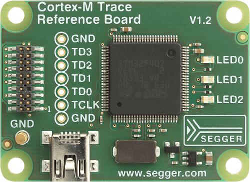
하드웨어
Board 정보는 SEGGER website, processor 정보와 datasheet는 STM32F407VE page에서 확인할 수 있습니다.
지원 기능
SEGGER-TRB-STM32F407 board configuration은 다음 hardware 기능을 지원합니다.
| Interface | Controller | Driver / Component |
|---|---|---|
| NVIC | on-chip | nested vectored interrupt controller |
| SYSTICK | on-chip | system clock |
| GPIO | on-chip | gpio |
| WATCHDOG | on-chip | independent watchdog |
| COUNTER | on-chip | rtc |
| RNG | on-chip | True Random Number Generator |
그 밖의 hardware 기능은 아직 이 board에서 활성화되지 않았습니다.
Pin mapping
LED
LED0 (green) = PA8LED1 (green) = PA9LED2 (green) = PA10
JTAG/SWD debug external connector
| Pin # | Signal Name | Pin # | Signal Name |
|---|---|---|---|
| 1 | VTref | 2 | SWDIO/TMS |
| 3 | GND | 4 | SWCLK/TCK |
| 5 | GND | 6 | SWO/TDO |
| 7 | --- | 8 | TDI |
| 9 | NC | 10 | nRESET |
| 11 | 5V-Supply | 12 | TRACECLK |
| 13 | 5V-Supply | 14 | TRACEDATA[0] |
| 15 | GND | 16 | TRACEDATA[1] |
| 17 | GND | 18 | TRACEDATA[2] |
| 19 | GND | 20 | TRACEDATA[3] |
System clock
SEGGER-STM32F407-TRB에는 external oscillator 하나가 있으며 main clock frequency는 12 MHz입니다. Processor가 HSE를 설정해 master clock을 구동하며 최대 168 MHz까지 설정할 수 있습니다.
Programming과 debugging
이 board는 SEGGER Trace-Pro debugger 시험용으로 특별히 설계되었으므로 다음 예제는 J-Trace 또는 J-Link 사용을 가정합니다.
Application flash
J-Trace/J-Link USB dongle을 host computer와 board JTAG port에 연결한 뒤 blinky application을 build하고 flash합니다.
west build -b segger_trb_stm32f407 samples/basic/blinky
west flash
Board를 reset하면 LED0가 1초 간격으로 깜박여야 합니다.
Debugging
blinky application을 debugger로 실행합니다.
west debugSource
출처
영어 원문에는 문단, 문서 지시문, 표, 코드, 코드 심벌, 경로를 그대로 보존했습니다.