Part 1
요약·해설
ASM2364와 LPC11U67의 역할 분담, LP5030 RGB LED, 지원 interface, IOCON pin과 ST-Link/OpenOCD 절차를 설명합니다.
NXP LPC11U67 · Cortex-M0+
ASM2364 · USB-to-PCIe
LP5030 · RGB LED × 6
SWD J2 · OpenOCD · ST-Link
Part 2
접을 수 있는 영어 원문 전체
영어 원문 전체 펼치기
420AB9041FA901E675EDC2863145F1BD9CADB5126833074867A8FD6DF463A136
.. _faze:

Seagate FireCuda Gaming SSD (FaZe) board
########################################

Overview
********

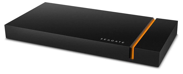
The FaZe board can be found in the Seagate FireCuda Gaming SSD devices. A NVMe
SSD and two chips are embedded: an ASMedia ASM2364 USB-to-PCIe bridge controller
and a NXP LPC11U67 MCU. The former is handling the USB type-C to SSD I/Os while
the latter is dedicated to the LED effects. The two chips are connected together
through I2C and GPIOs.

This Zephyr port is running on the NXP LPC11U67 MCU.

.. image:: ../../../../../../../boards/seagate/faze/doc/firecuda-gaming-ssd.jpg
   :align: center
   :alt: Seagate FireCuda Gaming SSD

Hardware
********

- NXP LPC11U67 MCU (LQFP48 package):

  - ARM Cortex-M0+
  - 20 KB SRAM: 16 KB (SRAM0) + 2 KB (SRAM1) + 2KB (USB SRAM)
  - 128 KB on-chip flash
  - 4 KB on-chip EEPROM

- External devices connected to the NXP LPC11U67 MCU:

  - ASMedia ASM2364 USB-to-PCIe bridge (I2C master on port O).
  - 6 RGB LEDs connected to a TI LP5030 LED controller (I2C device on
    port 1).
  - 1 white LED (SSD activity blinking).

More information can be found here:

- `LPC11UXX SoC Website`_
- `LPC11U6X Datasheet`_
- `LPC11U6X Reference Manual`_

Supported Features
==================

All the hardware features available on the FaZe board are supported in Zephyr.

+-----------+------------+-------------------------------------+
| Interface | Controller | Driver/Component                    |
+===========+============+=====================================+
| NVIC      | on-chip    | nested vector interrupt controller  |
+-----------+------------+-------------------------------------+
| SYSTICK   | on-chip    | systick                             |
+-----------+------------+-------------------------------------+
| IOCON     | on-chip    | pinmux                              |
+-----------+------------+-------------------------------------+
| CLOCK     | on-chip    | clock and reset control             |
+-----------+------------+-------------------------------------+
| GPIO      | on-chip    | gpio                                |
+-----------+------------+-------------------------------------+
| I2C       | on-chip    | i2c master/slave controller         |
+-----------+------------+-------------------------------------+
| UART      | on-chip    | serial port-polling;                |
|           |            | serial port interrupt               |
+-----------+------------+-------------------------------------+
| EEPROM    | on-chip    | eeprom                              |
+-----------+------------+-------------------------------------+

Connections and IOs
===================

The IOCON controller can be used to configure the LPC11U67 pins.

+---------+-----------------+----------------------------+
| Name    | Function        | Usage                      |
+=========+=================+============================+
| PIO0_2  | GPIO            | ASM2364 interrupt          |
+---------+-----------------+----------------------------+
| PIO0_4  | I2C0            | I2C0 SCL                   |
+---------+-----------------+----------------------------+
| PIO0_5  | I2C0            | I2C0 SDA                   |
+---------+-----------------+----------------------------+
| PIO0_7  | I2C1            | I2C1 SCL                   |
+---------+-----------------+----------------------------+
| PIO0_18 | UART            | USART0 RX                  |
+---------+-----------------+----------------------------+
| PIO0_19 | UART            | USART0 TX                  |
+---------+-----------------+----------------------------+
| PIO0_20 | GPIO            | USB sleep                  |
+---------+-----------------+----------------------------+
| PIO1_23 | GPIO            | SSD activity white LED     |
+---------+-----------------+----------------------------+
| PIO1_24 | I2C1            | I2C1 SDA                   |
+---------+-----------------+----------------------------+

Programming and Debugging
*************************

Flashing
========

The NXP LPC11U67 MCU can be flashed by connecting an external debug probe to
the SWD port (on-board 4-pins J2 header). In the default OpenOCD configuration
(:zephyr_file:`boards/seagate/faze/support/openocd.cfg`) the ST Link interface is selected.
You may need to replace it with the interface of your debug probe.

Once the debug probe is connected to both the FaZe board and your host computer
then you can simply run the ``west flash`` command to write a firmware image you
built into flash.

Debugging
=========

Please refer to the `Flashing`_ section and run the ``west debug`` command
instead of ``west flash``.

References
**********

- `LPC11UXX SoC Website`_
- `LPC11U6X Datasheet`_
- `LPC11U6X Reference Manual`_

.. _LPC11UXX SoC Website:
   https://www.nxp.com/products/processors-and-microcontrollers/arm-microcontrollers/general-purpose-mcus/lpc1100-cortex-m0-plus-m0/scalable-entry-level-32-bit-microcontroller-mcu-based-on-arm-cortex-m0-plus-and-cortex-m0-cores:LPC11U00

.. _LPC11U6X Datasheet:
   https://www.nxp.com/docs/en/data-sheet/LPC11U6X.pdf

.. _LPC11U6x Reference Manual:
   https://www.nxp.com/webapp/Download?colCode=UM10732
Part 3
한국어 전문 번역
개요
FaZe board는 Seagate FireCuda Gaming SSD 제품에서 찾을 수 있습니다. NVMe SSD와 두 chip, 즉 ASMedia ASM2364 USB-to-PCIe bridge controller와 NXP LPC11U67 MCU가 내장되어 있습니다. ASM2364는 USB Type-C와 SSD 사이의 I/O를 처리하고, LPC11U67은 LED effect 전용입니다. 두 chip은 I2C와 GPIO를 통해 서로 연결됩니다.
이 Zephyr port는 NXP LPC11U67 MCU에서 실행됩니다.
하드웨어
NXP LPC11U67 MCU
- LQFP48 package
- ARM Cortex-M0+
- 20 KB SRAM: 16 KB SRAM0 + 2 KB SRAM1 + 2 KB USB SRAM
- 128 KB on-chip flash
- 4 KB on-chip EEPROM
LPC11U67에 연결된 외부 device
- ASMedia ASM2364 USB-to-PCIe bridge: port 0의 I2C master
- TI LP5030 LED controller에 연결된 RGB LED 6개: port 1의 I2C device
- SSD activity를 표시하는 white LED 1개
추가 정보는 LPC11UXX SoC website, LPC11U6X datasheet, LPC11U6X reference manual에서 확인할 수 있습니다.
지원 기능
FaZe board에서 사용할 수 있는 모든 hardware 기능을 Zephyr가 지원합니다.
| Interface | Controller | Driver / Component |
|---|---|---|
| NVIC | on-chip | nested vector interrupt controller |
| SYSTICK | on-chip | systick |
| IOCON | on-chip | pinmux |
| CLOCK | on-chip | clock and reset control |
| GPIO | on-chip | gpio |
| I2C | on-chip | i2c master/slave controller |
| UART | on-chip | serial port-polling; serial port interrupt |
| EEPROM | on-chip | eeprom |
연결과 I/O
IOCON controller를 사용해 LPC11U67 pin을 설정할 수 있습니다.
| Name | Function | Usage |
|---|---|---|
| PIO0_2 | GPIO | ASM2364 interrupt |
| PIO0_4 | I2C0 | I2C0 SCL |
| PIO0_5 | I2C0 | I2C0 SDA |
| PIO0_7 | I2C1 | I2C1 SCL |
| PIO0_18 | UART | USART0 RX |
| PIO0_19 | UART | USART0 TX |
| PIO0_20 | GPIO | USB sleep |
| PIO1_23 | GPIO | SSD activity white LED |
| PIO1_24 | I2C1 | I2C1 SDA |
Programming과 debugging
Flashing
NXP LPC11U67 MCU는 외부 debug probe를 SWD port, 즉 board의 4-pin J2 header에 연결해 flash할 수 있습니다. 기본 OpenOCD configuration인 boards/seagate/faze/support/openocd.cfg에서는 ST-Link interface가 선택되어 있습니다. 사용하는 debug probe에 맞는 interface로 교체해야 할 수 있습니다.
Debug probe를 FaZe board와 host computer 양쪽에 연결한 뒤 west flash를 실행하면 build한 firmware image를 flash에 기록할 수 있습니다.
Debugging
앞의 flashing 절차를 따르되 west flash 대신 west debug를 실행합니다.
참고 자료
Source
출처
영어 원문에는 문단, 문서 지시문, 표, 코드, 코드 심벌, 경로를 그대로 보존했습니다.