Part 1
요약·해설
Pico와 Pico W 차이, 지원 peripheral 14종, DTS pin route, PIO SPI, J-Link·OpenOCD·UF2 workflow를 단계별로 설명합니다.
RP2040 · dual Cortex-M0+ · 133 MHz
264 KB SRAM · 2 MB QSPI flash
J-Link · OpenOCD · UF2 drag-and-drop
Part 2
접을 수 있는 영어 원문 전체
영어 원문 전체 펼치기
85F88654B6AD10D40418BED5397CED6909A2F77B93587B68287C6E9ADDDC98B0
.. _rpi_pico:

Raspberry Pi Pico
#################

Overview
********

The Raspberry Pi Pico and Pico W are small, low-cost, versatile boards from
Raspberry Pi. They are equipped with an RP2040 SoC, an on-board LED,
a USB connector, and an SWD interface. The Pico W additionally contains an
Infineon CYW43439 2.4 GHz Wi-Fi/Bluetooth module. The USB bootloader allows the
ability to flash without any adapter, in a drag-and-drop manner.
It is also possible to flash and debug the boards with their SWD interface,
using an external adapter.

Hardware
********
- Dual core Arm Cortex-M0+ processor running up to 133MHz
- 264KB on-chip SRAM
- 2MB on-board QSPI flash with XIP capabilities
- 26 GPIO pins
- 3 Analog inputs
- 2 UART peripherals
- 2 SPI controllers
- 2 I2C controllers
- 16 PWM channels
- USB 1.1 controller (host/device)
- 8 Programmable I/O (PIO) for custom peripherals
- On-board LED
- 1 Watchdog timer peripheral
- Infineon CYW43439 2.4 GHz Wi-Fi chip (Pico W only)


.. figure:: ../../../../../../../boards/raspberrypi/rpi_pico/doc/img/rpi_pico.jpg
     :align: center
     :alt: Raspberry Pi Pico


.. figure:: ../../../../../../../boards/raspberrypi/rpi_pico/doc/img/rpi_pico_w.jpg
     :align: center
     :alt: Raspberry Pi Pico W

     Raspberry Pi Pico (above) and Pico W (below)
     (Images courtesy of Raspberry Pi)

Supported Features
==================

The rpi_pico board configuration supports the following
hardware features:

.. list-table::
   :header-rows: 1

   * - Peripheral
     - Kconfig option
     - Devicetree compatible
   * - NVIC
     - N/A
     - :dtcompatible:`arm,v6m-nvic`
   * - UART
     - :kconfig:option:`CONFIG_SERIAL`
     - :dtcompatible:`raspberrypi,pico-uart`
   * - GPIO
     - :kconfig:option:`CONFIG_GPIO`
     - :dtcompatible:`raspberrypi,pico-gpio`
   * - ADC
     - :kconfig:option:`CONFIG_ADC`
     - :dtcompatible:`raspberrypi,pico-adc`
   * - I2C
     - :kconfig:option:`CONFIG_I2C`
     - :dtcompatible:`snps,designware-i2c`
   * - SPI
     - :kconfig:option:`CONFIG_SPI`
     - :dtcompatible:`raspberrypi,pico-spi`
   * - USB Device
     - :kconfig:option:`CONFIG_USB_DEVICE_STACK`
     - :dtcompatible:`raspberrypi,pico-usbd`
   * - HWINFO
     - :kconfig:option:`CONFIG_HWINFO`
     - N/A
   * - Watchdog Timer (WDT)
     - :kconfig:option:`CONFIG_WATCHDOG`
     - :dtcompatible:`raspberrypi,pico-watchdog`
   * - PWM
     - :kconfig:option:`CONFIG_PWM`
     - :dtcompatible:`raspberrypi,pico-pwm`
   * - Flash
     - :kconfig:option:`CONFIG_FLASH`
     - :dtcompatible:`raspberrypi,pico-flash`
   * - Clock controller
     - :kconfig:option:`CONFIG_CLOCK_CONTROL`
     - :dtcompatible:`raspberrypi,pico-clock-controller`
   * - UART (PIO)
     - :kconfig:option:`CONFIG_SERIAL`
     - :dtcompatible:`raspberrypi,pico-uart-pio`
   * - SPI (PIO)
     - :kconfig:option:`CONFIG_SPI`
     - :dtcompatible:`raspberrypi,pico-spi-pio`

Pin Mapping
===========

The peripherals of the RP2040 SoC can be routed to various pins on the board.
The configuration of these routes can be modified through DTS. Please refer to
the datasheet to see the possible routings for each peripheral.

External pin mapping on the Pico W is identical to the Pico, but note that internal
RP2040 GPIO lines 23, 24, 25, and 29 are routed to the Infineon module on the W.
Since GPIO 25 is routed to the on-board LED on the Pico, but to the Infineon module
on the Pico W, the "blinky" sample program does not work on the W (use hello_world for
a simple test program instead).

Default Zephyr Peripheral Mapping:
----------------------------------

.. rst-class:: rst-columns

- UART0_TX : P0
- UART0_RX : P1
- I2C0_SDA : P4
- I2C0_SCL : P5
- I2C1_SDA : P14
- I2C1_SCL : P15
- SPI0_RX : P16
- SPI0_CSN : P17
- SPI0_SCK : P18
- SPI0_TX : P19
- ADC_CH0 : P26
- ADC_CH1 : P27
- ADC_CH2 : P28
- ADC_CH3 : P29

Programmable I/O (PIO)
**********************
The RP2040 SoC comes with two PIO periherals. These are two simple
co-processors that are designed for I/O operations. The PIOs run
a custom instruction set, generated from a custom assembly language.
PIO programs are assembled using `pioasm`, a tool provided by Raspberry Pi.

Zephyr does not (currently) assemble PIO programs. Rather, they should be
manually assembled and embedded in source code. An example of how this is done
can be found at `drivers/serial/uart_rpi_pico_pio.c`.

Sample:  SPI via PIO
====================

The :zephyr_file:`samples/sensor/bme280/README.rst` sample includes a
demonstration of using the PIO SPI driver to communicate with an
environmental sensor.  The PIO SPI driver supports using any
combination of GPIO pins for an SPI bus, as well as allowing up to
four independent SPI buses on a single board (using the two SPI
devices as well as both PIO devices).

Programming and Debugging
*************************

Flashing
========

Using SEGGER JLink
------------------

You can Flash the rpi_pico with a SEGGER JLink debug probe as described in
:ref:`Building, Flashing and Debugging <west-flashing>`.

Here is an example of building and flashing the :zephyr:code-sample:`blinky` application.

.. zephyr-app-commands::
   :zephyr-app: samples/basic/blinky
   :board: rpi_pico
   :goals: build

.. code-block:: bash

  west flash --runner jlink

Using OpenOCD
-------------

To use CMSIS-DAP, You must configure **udev**.

Create a file in /etc/udev.rules.d with any name, and write the line below.

.. code-block:: bash

   ATTRS{idVendor}=="2e8a", ATTRS{idProduct}=="000c", MODE="660", GROUP="plugdev", TAG+="uaccess"

This example is valid for the case that the user joins to `plugdev` groups.

The Raspberry Pi Pico has an SWD interface that can be used to program
and debug the on board RP2040. This interface can be utilized by OpenOCD.
To use it with the RP2040, OpenOCD version 0.12.0 or later is needed.

If you are using a Debian based system (including RaspberryPi OS, Ubuntu. and more),
using the `pico_setup.sh`_ script is a convenient way to set up the forked version of OpenOCD.

Depending on the interface used (such as JLink), you might need to
checkout to a branch that supports this interface, before proceeding.
Build and install OpenOCD as described in the README.

Here is an example of building and flashing the :zephyr:code-sample:`blinky` application.

.. zephyr-app-commands::
   :zephyr-app: samples/basic/blinky
   :board: rpi_pico
   :goals: build flash
   :gen-args: -DOPENOCD=/usr/local/bin/openocd -DOPENOCD_DEFAULT_PATH=/usr/local/share/openocd/scripts -DRPI_PICO_DEBUG_ADAPTER=cmsis-dap

Set the environment variables **OPENOCD** to `/usr/local/bin/openocd`
and **OPENOCD_DEFAULT_PATH** to `/usr/local/share/openocd/scripts`. This should work
with the OpenOCD that was installed with the default configuration.
This configuration also works with an environment that is set up by the `pico_setup.sh`_ script.

**RPI_PICO_DEBUG_ADAPTER** specifies what debug adapter is used for debugging.

If **RPI_PICO_DEBUG_ADAPTER** was not assigned, `cmsis-dap` is used by default.
The other supported adapters are `raspberrypi-swd`, `jlink` and `blackmagicprobe`.
How to connect `cmsis-dap` and `raspberrypi-swd` is described in `Getting Started with Raspberry Pi Pico`_.
Any other SWD debug adapter maybe also work with this configuration.

The value of **RPI_PICO_DEBUG_ADAPTER** is cached, so it can be omitted from
`west flash` and `west debug` if it was previously set while running `west build`.

**RPI_PICO_DEBUG_ADAPTER** is used in an argument to OpenOCD as `"source [find interface/${RPI_PICO_DEBUG_ADAPTER}.cfg]"`.
Thus, **RPI_PICO_DEBUG_ADAPTER** needs to be assigned the file name of the debug adapter.

You can also flash the board with the following
command that directly calls OpenOCD (assuming a SEGGER JLink adapter is used):

.. code-block:: console

   $ openocd -f interface/jlink.cfg -c 'transport select swd' -f target/rp2040.cfg -c "adapter speed 2000" -c 'targets rp2040.core0' -c 'program path/to/zephyr.elf verify reset exit'

Using UF2
---------

If you don't have an SWD adapter, you can flash the Raspberry Pi Pico with
a UF2 file. By default, building an app for this board will generate a
`build/zephyr/zephyr.uf2` file. If the Pico is powered on with the `BOOTSEL`
button pressed, it will appear on the host as a mass storage device. The
UF2 file should be drag-and-dropped to the device, which will flash the Pico.

Debugging
=========

The SWD interface can also be used to debug the board. To achieve this, you can
either use SEGGER JLink or OpenOCD.

Using SEGGER JLink
------------------

Use a SEGGER JLink debug probe and follow the instruction in
:ref:`Building, Flashing and Debugging<west-debugging>`.


Using OpenOCD
-------------

Install OpenOCD as described for flashing the board.

Here is an example for debugging the :zephyr:code-sample:`blinky` application.

.. zephyr-app-commands::
   :zephyr-app: samples/basic/blinky
   :board: rpi_pico
   :maybe-skip-config:
   :goals: debug
   :gen-args: -DOPENOCD=/usr/local/bin/openocd -DOPENOCD_DEFAULT_PATH=/usr/local/share/openocd/scripts -DRPI_PICO_DEBUG_ADAPTER=raspberrypi-swd

As with flashing, you can specify the debug adapter by specifying **RPI_PICO_DEBUG_ADAPTER**
at `west build` time. No needs to specify it at `west debug` time.

You can also debug with OpenOCD and gdb launching from command-line.
Run the following command:

.. code-block:: console

   $ openocd -f interface/jlink.cfg -c 'transport select swd' -f target/rp2040.cfg -c "adapter speed 2000" -c 'targets rp2040.core0'

On another terminal, run:

.. code-block:: console

   $ gdb-multiarch

Inside gdb, run:

.. code-block:: console

   (gdb) tar ext :3333
   (gdb) file path/to/zephyr.elf

You can then start debugging the board.

.. target-notes::

.. _pico_setup.sh:
   https://raw.githubusercontent.com/raspberrypi/pico-setup/master/pico_setup.sh

.. _Getting Started with Raspberry Pi Pico:
  https://datasheets.raspberrypi.com/pico/getting-started-with-pico.pdf
Part 3
한국어 전문 번역
개요
Raspberry Pi Pico와 Pico W는 Raspberry Pi가 만든 작고 저렴하며 용도가 다양한 보드입니다. 두 보드 모두 RP2040 SoC, on-board LED, USB connector, SWD interface를 갖춥니다. Pico W에는 Infineon CYW43439 2.4 GHz Wi-Fi/Bluetooth module이 추가됩니다. USB bootloader를 이용하면 adapter 없이 drag-and-drop 방식으로 flash할 수 있습니다. 외부 adapter와 SWD interface로 flash 및 debug하는 것도 가능합니다.
하드웨어
- 최대 133 MHz로 동작하는 dual-core Arm Cortex-M0+ processor
- On-chip SRAM 264 KB
- XIP를 지원하는 on-board QSPI flash 2 MB
- GPIO pin 26개
- Analog input 3개
- UART peripheral 2개
- SPI controller 2개
- I2C controller 2개
- PWM channel 16개
- USB 1.1 host/device controller
- Custom peripheral용 Programmable I/O(PIO) 8개
- On-board LED
- Watchdog timer peripheral 1개
- Infineon CYW43439 2.4 GHz Wi-Fi chip(Pico W만 해당)
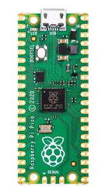
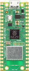
지원 기능
rpi_pico board configuration은 다음 hardware feature를 지원합니다.
| 주변장치 | Kconfig option | Devicetree compatible |
|---|---|---|
NVIC | N/A | arm,v6m-nvic |
UART | CONFIG_SERIAL | raspberrypi,pico-uart |
GPIO | CONFIG_GPIO | raspberrypi,pico-gpio |
ADC | CONFIG_ADC | raspberrypi,pico-adc |
I2C | CONFIG_I2C | snps,designware-i2c |
SPI | CONFIG_SPI | raspberrypi,pico-spi |
USB Device | CONFIG_USB_DEVICE_STACK | raspberrypi,pico-usbd |
HWINFO | CONFIG_HWINFO | N/A |
Watchdog Timer (WDT) | CONFIG_WATCHDOG | raspberrypi,pico-watchdog |
PWM | CONFIG_PWM | raspberrypi,pico-pwm |
Flash | CONFIG_FLASH | raspberrypi,pico-flash |
Clock controller | CONFIG_CLOCK_CONTROL | raspberrypi,pico-clock-controller |
UART (PIO) | CONFIG_SERIAL | raspberrypi,pico-uart-pio |
SPI (PIO) | CONFIG_SPI | raspberrypi,pico-spi-pio |
Pin 매핑
RP2040 SoC peripheral은 보드의 여러 pin으로 route할 수 있습니다. 이 route configuration은 DTS로 수정할 수 있으며, peripheral별 가능한 route는 datasheet를 참고합니다.
Pico W의 외부 pin mapping은 Pico와 같지만, W에서는 내부 RP2040 GPIO line 23, 24, 25, 29가 Infineon module로 연결된다는 점에 유의해야 합니다. Pico에서는 GPIO 25가 on-board LED로 연결되지만 Pico W에서는 Infineon module로 연결되므로, blinky sample은 W에서 동작하지 않습니다. 간단한 test에는 대신 hello_world를 사용합니다.
기본 Zephyr peripheral 매핑
UART0_TX : P0UART0_RX : P1I2C0_SDA : P4I2C0_SCL : P5I2C1_SDA : P14I2C1_SCL : P15SPI0_RX : P16SPI0_CSN : P17SPI0_SCK : P18SPI0_TX : P19ADC_CH0 : P26ADC_CH1 : P27ADC_CH2 : P28ADC_CH3 : P29
Programmable I/O(PIO)
RP2040 SoC에는 PIO peripheral이 2개 있습니다. 이들은 I/O operation용으로 설계된 단순한 coprocessor입니다. PIO는 custom assembly language로부터 생성한 custom instruction set을 실행합니다. PIO program은 Raspberry Pi가 제공하는 pioasm tool로 assemble합니다.
Zephyr는 현재 PIO program을 assemble하지 않습니다. 대신 수동으로 assemble하여 source code에 embed해야 합니다. 구현 예시는 drivers/serial/uart_rpi_pico_pio.c에서 확인할 수 있습니다.
Sample: PIO를 통한 SPI
samples/sensor/bme280/README.rst sample은 PIO SPI driver로 environmental sensor와 통신하는 예를 포함합니다. PIO SPI driver는 GPIO pin을 어떤 조합으로든 SPI bus에 사용할 수 있으며, 두 SPI device와 두 PIO device를 사용해 단일 보드에서 서로 독립적인 SPI bus를 최대 4개까지 구성할 수 있습니다.
프로그래밍과 디버깅
플래시
SEGGER J-Link 사용
“Building, Flashing and Debugging” 절차에 따라 SEGGER J-Link debug probe로 rpi_pico를 flash할 수 있습니다. 다음은 blinky application을 build하고 flash하는 예입니다.
west build -b rpi_pico samples/basic/blinkywest flash --runner jlinkOpenOCD 사용
CMSIS-DAP을 사용하려면 udev를 구성해야 합니다. /etc/udev.rules.d에 원하는 이름의 file을 만들고 다음 line을 작성합니다.
ATTRS{idVendor}=="2e8a", ATTRS{idProduct}=="000c", MODE="660", GROUP="plugdev", TAG+="uaccess"이 예시는 사용자가 plugdev group에 가입되어 있다고 가정합니다.
Raspberry Pi Pico의 SWD interface로 on-board RP2040을 program하고 debug할 수 있으며 OpenOCD가 이 interface를 사용할 수 있습니다. RP2040에는 OpenOCD 0.12.0 이상이 필요합니다. Debian 계열 system(Raspberry Pi OS, Ubuntu 등)에서는 pico_setup.sh script를 사용하면 fork된 OpenOCD version을 편리하게 설정할 수 있습니다.
J-Link 같은 interface를 사용한다면 진행 전에 해당 interface를 지원하는 branch로 checkout해야 할 수도 있습니다. README에 따라 OpenOCD를 build하고 설치합니다.
다음은 blinky application을 build하고 flash하는 예입니다.
west build -b rpi_pico samples/basic/blinky -- -DOPENOCD=/usr/local/bin/openocd -DOPENOCD_DEFAULT_PATH=/usr/local/share/openocd/scripts -DRPI_PICO_DEBUG_ADAPTER=cmsis-dap
west flashOPENOCD는 /usr/local/bin/openocd, OPENOCD_DEFAULT_PATH는 /usr/local/share/openocd/scripts로 설정합니다. 이는 default configuration으로 설치했거나 pico_setup.sh로 설정한 OpenOCD에서 동작합니다.
RPI_PICO_DEBUG_ADAPTER는 사용할 debug adapter를 지정합니다. 지정하지 않으면 기본값은 cmsis-dap입니다. 그 밖에 raspberrypi-swd, jlink, blackmagicprobe를 지원합니다. cmsis-dap과 raspberrypi-swd 연결법은 Getting Started with Raspberry Pi Pico에 설명되어 있습니다. 다른 SWD debug adapter도 이 구성에서 동작할 수 있습니다.
RPI_PICO_DEBUG_ADAPTER 값은 cache되므로 이전 west build에서 설정했다면 west flash와 west debug에서 생략할 수 있습니다. OpenOCD argument에는 source [find interface/${RPI_PICO_DEBUG_ADAPTER}.cfg] 형태로 사용되므로 debug adapter의 file name을 값으로 지정해야 합니다.
SEGGER J-Link adapter를 사용한다고 가정하면 OpenOCD를 직접 호출해 보드를 flash할 수도 있습니다.
$ openocd -f interface/jlink.cfg -c 'transport select swd' -f target/rp2040.cfg -c "adapter speed 2000" -c 'targets rp2040.core0' -c 'program path/to/zephyr.elf verify reset exit'UF2 사용
SWD adapter가 없다면 UF2 file로 Raspberry Pi Pico를 flash할 수 있습니다. 이 보드용 application을 build하면 기본적으로 build/zephyr/zephyr.uf2가 생성됩니다. BOOTSEL button을 누른 채 Pico 전원을 켜면 host에 mass storage device로 나타납니다. UF2 file을 장치로 drag-and-drop하면 Pico가 flash됩니다.
디버깅
SWD interface는 보드 debug에도 사용할 수 있습니다. SEGGER J-Link 또는 OpenOCD를 선택할 수 있습니다.
SEGGER J-Link 사용
SEGGER J-Link debug probe를 연결하고 “Building, Flashing and Debugging”의 debug 절차를 따릅니다.
OpenOCD 사용
보드 flash 절차에서 설명한 대로 OpenOCD를 설치합니다. 다음은 blinky application을 debug하는 예입니다.
west build -b rpi_pico samples/basic/blinky -- -DOPENOCD=/usr/local/bin/openocd -DOPENOCD_DEFAULT_PATH=/usr/local/share/openocd/scripts -DRPI_PICO_DEBUG_ADAPTER=raspberrypi-swd
west debug
Flash 때와 마찬가지로 west build 시점에 RPI_PICO_DEBUG_ADAPTER를 지정할 수 있습니다. west debug에서는 다시 지정할 필요가 없습니다.
Command line에서 OpenOCD와 GDB를 직접 실행해 debug할 수도 있습니다. 먼저 다음 명령을 실행합니다.
$ openocd -f interface/jlink.cfg -c 'transport select swd' -f target/rp2040.cfg -c "adapter speed 2000" -c 'targets rp2040.core0'다른 terminal에서 다음을 실행합니다.
$ gdb-multiarchGDB 안에서 다음 명령을 실행하면 보드 debug를 시작할 수 있습니다.
(gdb) tar ext :3333
(gdb) file path/to/zephyr.elf
Source
출처
영어 원문에는 문단, 문서 지시문, 표, 코드, 코드 심벌, 경로를 그대로 보존했습니다.