Part 1
요약·해설
풍부한 산업 interface, M7 memory 5영역, ITCM/DDR chosen 설정과 U-Boot·JTAG 절차를 설명합니다.
i.MX8M Plus · 4×A53 + M7
ITCM · DDR
U-Boot only in v3.7.0 docs
Part 2
접을 수 있는 영어 원문 전체
영어 원문 전체 펼치기
B6917541428156EDE9EBB7B54389AF10000F578C08B14ADE9521766979BCBB73
.. _mimx8mp_phyboard_pollux:

PhyBOARD Pollux (NXP i.MX8M Plus)
#################################

Overview
********

The PhyBOARD Pollux is based upon the PhyCore-i.MX8M Plus SOM which is based on
the NXP i.MX8M Plus SoC. The SoC includes four Coretex-A53 cores and one
Coretex-M7 core for real time applications like Zephyr. The PhyBOARD Pollux
can be used for various applications like SmartHomes, Industry 4.0, IoT etc.
It features a lots of interfaces and computing capacity. It can be used as
a reference, to develop or in the final product too.


Board features:

- Memory:

   - RAM: 256MB - 8GB LPDDR4
   - EEPROM: 4kB - 32kB
   - eMMC: 4GB - 64GB (eMMC 5.1)
   - SPI NOR Flash: 4MB - 256MB
- Interfaces:

   - Ethernet: 2x 10/100/1000BASE-T (1x TSN Support)
   - USB: 2x 3.0 Host
   - Serial: 1x RS232 / RS485 Full Duplex / Half Duplex
   - CAN: 2x CAN FD
   - Digital I/O: via Expansion Connector
   - PCIe: 1x miniPCIe
   - MMX/SD/SDIO: microSD slot
   - Display: LVDS(1x4 or 1x8), MIPI DSI(1x4), HDMI
   - Audio: SAI
   - Camera: 2x MIPI CSI-2 (PhyCAM-M)
   - Expansion Bus: I2C, SPI, SDIO, UART, USB
   - JTAG: via PEB-EVAL-01
- LEDs:

   - 1x Multicolor Status LED via I2C


.. image:: ../../../../../../../boards/phytec/mimx8mp_phyboard_pollux/doc/img/Phyboard_Pollux.jpg
   :width: 720px
   :align: center
   :height: 405px
   :alt: PhyBOARD Pollux

More information about the board can be found at the
`PHYTEC website`_.

Supported Features
==================

The Zephyr mimx8mp_phyboard_polis board configuration supports the following hardware
features:

+-----------+------------+-------------------------------------+
| Interface | Controller | Driver/Component                    |
+===========+============+=====================================+
| NVIC      | on-chip    | nested vector interrupt controller  |
+-----------+------------+-------------------------------------+
| SYSTICK   | on-chip    | systick                             |
+-----------+------------+-------------------------------------+
| CLOCK     | on-chip    | clock_control                       |
+-----------+------------+-------------------------------------+
| PINMUX    | on-chip    | pinmux                              |
+-----------+------------+-------------------------------------+
| UART      | on-chip    | serial port-polling;                |
|           |            | serial port-interrupt               |
+-----------+------------+-------------------------------------+
| GPIO      | on-chip    | GPIO output                         |
|           |            | GPIO input                          |
+-----------+------------+-------------------------------------+

The default configuration can be found in the defconfig file:
:zephyr_file:`boards/phytec/mimx8mp_phyboard_pollux/mimx8mp_phyboard_pollux_mimx8ml8_m7_defconfig`.

It's recommended to disable peripherals used by the M7-Core on the host running
on the Linux host.

Other hardware features are not currently supported with Zephyr on the
M7-Core.

Connections and IOs
===================

The following Compontens are tested and working correctly.

UART
----

+---------------+-----------------+-----------------------------------+
| Board Name    | SoM Name        | Usage                             |
+===============+=================+===================================+
| Debug USB(A53)| UART1           | UART Debug Console via USB        |
+---------------+-----------------+-----------------------------------+
| Wo WiFi Module| UART3           | UART to WiFi/BLE Module           |
+---------------+-----------------+-----------------------------------+
| Debug USB(M4) | UART4           | UART Debug Console via USB        |
+---------------+-----------------+-----------------------------------+

.. note::
  Please note, that the, to UART3 connected, Wifi/BLE Module isn't working with
  Zephyr yet. UART3 can also be used through pin 31(RX) and 33(TX) of the
  X6 Connector.

GPIO
----

The pinmuxing for the GPIOs is the standard pinmuxing of the mimx8mp devicetree
created by NXP. You can find it here:

:zephyr_file:`dts/arm/nxp/nxp_imx8ml_m7.dtsi`.

The Pinout of the PhyBOARD Polis can be found here:

`PHYTEC website`_

Programming and Debugging
*************************

The i.MX8MP does not have a separate flash for the M7-Core. Because of this
the A53-Core has to load the program for the M7-Core to the right memory
address, set the PC and start the processor.
This can only by done with u-boot at the moment. We are working on our BSP to
enable remoteproc support.

The M7 can use up to 3 different RAMs (currently, only two configurations are
supported: ITCM and DDR). These are the memory mapping for A53 and M7:

+------------+-------------------------+------------------------+-----------------------+----------------------+
| Region     | Cortex-A53              | Cortex-M7 (System Bus) | Cortex-M7 (Code Bus)  | Size                 |
+============+=========================+========================+=======================+======================+
| OCRAM      | 0x00900000-0x0098FFFF   | 0x20200000-0x2028FFFF  | 0x00900000-0x0098FFFF | 576KB                |
+------------+-------------------------+------------------------+-----------------------+----------------------+
| DTCM       | 0x00800000-0x0081FFFF   | 0x20000000-0x2001FFFF  |                       | 128KB                |
+------------+-------------------------+------------------------+-----------------------+----------------------+
| ITCM       | 0x007E0000-0x007FFFFF   |                        | 0x00000000-0x0001FFFF | 128KB                |
+------------+-------------------------+------------------------+-----------------------+----------------------+
| OCRAM_S    | 0x00180000-0x00188FFF   | 0x20180000-0x20188FFF  | 0x00180000-0x00188FFF | 36KB                 |
+------------+-------------------------+------------------------+-----------------------+----------------------+
| DDR        | 0x80000000-0x803FFFFF   | 0x80200000-0x803FFFFF  | 0x80000000-0x801FFFFF | 2MB                  |
+------------+-------------------------+------------------------+-----------------------+----------------------+

For more information about memory mapping see the
`i.MX 8M Plus Applications Processor Reference Manual`_  (section 2.1 to 2.3)

At compilation time you have to choose which memory region will be used. This
configuration is done in the devicetree and the defconfig / the config of your
program.

**By default Zephyr will use the TCM memory region.** You can configure it like
this for the DDR region:

In the devicetree overwrite the following nodes like this:

.. code-block:: DTS

   chosen {
      /* TCM */
      zephyr,flash = &itcm;
	   zephyr,sram = &dtcm;
   };

change it to

.. code-block:: DTS

   chosen {
      /* DDR */
      zephyr,flash = &ddr_code;
      zephyr,sram = &ddr_sys;
   };


In your prj.conf overwrite the configuration like this for the **DDR** memory
region:

.. code-block:: cfg

   CONFIG_CODE_DDR=y
   CONFIG_CODE_ITCM=n


Starting the M7-Core via U-Boot
===============================

Load the compiled zephyr.bin to memory address 0x4800000.
This should output something like this:

.. code-block:: console

   u-boot=> tftp 0x48000000 192.168.3.10:zephyr.bin
   Using ethernet@30be0000 device
   TFTP from server 192.168.3.10; our IP address is 192.168.3.11
   Filename 'zephyr.bin'.
   Load address: 0x48000000
   Loading: ##
            2 KiB/s
   done
   Bytes transferred = 27240 (6a68 hex)

Because it's not possible to load directly to the TCM memory area you have to
copy the binaries. The last argument given is the size of the file in bytes,
you can copy it from the output of the last command.

.. code-block:: console

   u-boot=> cp.b 0x48000000 0x7e0000 27240

And finaly starting the M7-Core at the right memory address:

.. code-block:: console

   u-boot=> bootaux 0x7e0000
   ## Starting auxiliary core stack = 0x20003A58, pc = 0x1FFE1905...

Debugging
=========

The PhyBOARD Polis can be debugged using a JTAG Debugger.
The easiest way to do that is to use a SEGGER JLink Debugger and Phytec's
``PEB-EVAL-01`` Shield, which can be directly connected to the JLink.
You can find the JLink Software package here: `JLink Software`_

.. figure:: ../../../../../../../boards/phytec/mimx8mp_phyboard_pollux/doc/img/PEB-EVAL-01.jpg
   :alt: PEB-EVAL-01
   :width: 350

   PEB-EVAL-01

To debug efficiently you have to use multiple terminals:

After connecting everything and building with west use this command while in
the directory of the program you build earlier to start a debug server:

.. code-block:: console

   host$ west debugserver

West automatically connects via the JLink to the Target and keeps open a
debug server.

Use another terminal, start gdb, connect to target and load Zephyr on the
target:

.. code-block:: console

   host$ gdb-multiarch build/zephyr/zephyr.elf -tui
   (gdb) targ rem :2331
   Remote debugging using :2331
   0x1ffe0008 in _vector_table ()
   (gdb) mon halt
   (gdb) mon reset
   (gdb) c
   Continuing.

The program can be debugged using standard gdb techniques.

References
==========

.. _PHYTEC website:
   https://www.phytec.de/produkte/single-board-computer/phyboard-pollux/

.. _i.MX 8M Plus Applications Processor Reference Manual:
   https://www.nxp.com/webapp/Download?colCode=IMX8MPRM

.. _JLink Software:
   https://www.segger.com/downloads/jlink/
Part 3
한국어 전문 번역
개요
PhyBOARD Pollux는 NXP i.MX8M Plus SoC 기반 PhyCORE-i.MX8M Plus SoM을 사용합니다. SoC에는 Cortex-A53 core 네 개와 Zephyr 같은 real-time application용 Cortex-M7 core 한 개가 있습니다. Smart home, Industry 4.0, IoT 등에 사용할 수 있고 interface와 computing capacity가 풍부하여 reference, development platform, final product로 활용할 수 있습니다.
보드 기능
- Memory: LPDDR4 256MB~8GB, EEPROM 4kB~32kB, eMMC 5.1 4GB~64GB, SPI NOR Flash 4MB~256MB
- Ethernet: 10/100/1000BASE-T 2개, 이 중 하나는 TSN 지원
- USB: USB 3.0 Host 2개
- Serial: full/half duplex RS232/RS485 1개
- CAN FD 2개, expansion connector digital I/O, mini PCIe 1개, microSD slot
- Display: LVDS(1x4 또는 1x8), MIPI DSI(1x4), HDMI
- Audio: SAI; Camera: MIPI CSI-2(PhyCAM-M) 2개
- Expansion bus: I2C, SPI, SDIO, UART, USB; JTAG: PEB-EVAL-01 경유
- I2C를 통한 multicolor status LED 1개
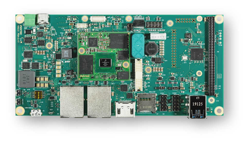
보드 정보는 PHYTEC 웹사이트에서 더 확인할 수 있습니다.
지원 기능
| 인터페이스 | 컨트롤러 | 드라이버/컴포넌트 |
|---|---|---|
NVIC | on-chip | nested vector interrupt controller |
SYSTICK | on-chip | systick |
CLOCK | on-chip | clock_control |
PINMUX | on-chip | pinmux |
UART | on-chip | serial port-polling; serial port-interrupt |
GPIO | on-chip | GPIO output; GPIO input |
기본 구성은 boards/phytec/mimx8mp_phyboard_pollux/mimx8mp_phyboard_pollux_mimx8ml8_m7_defconfig입니다. M7 core가 사용하는 peripheral은 Linux host에서 비활성화하는 것을 권장합니다. 표 밖의 다른 하드웨어 기능은 현재 M7용 Zephyr port에서 지원하지 않습니다.
연결과 I/O
UART
| 보드 이름 | SoM 이름 | 용도 |
|---|---|---|
| Debug USB(A53) | UART1 | USB UART debug console |
| WiFi module 연결 | UART3 | WiFi/BLE module용 UART |
| Debug USB(M4) | UART4 | USB UART debug console |
GPIO
GPIO pinmux는 NXP가 만든 i.MX8MP devicetree의 표준 설정이며 dts/arm/nxp/nxp_imx8ml_m7.dtsi에서 확인할 수 있습니다. 원문은 이 문단에서 보드 이름을 PhyBOARD Polis로 적지만 링크는 Pollux PHYTEC 페이지를 가리킵니다.
프로그래밍과 디버깅
i.MX8MP에는 M7 core 전용 flash가 없습니다. 따라서 A53 core가 M7 program을 올바른 memory address에 적재하고 PC를 설정한 뒤 processor를 시작해야 합니다. Zephyr 3.7.0 원문 시점에는 U-Boot로만 할 수 있고 PHYTEC BSP의 remoteproc 지원은 작업 중이라고 명시되어 있습니다.
M7은 최대 세 종류 RAM을 사용할 수 있지만 현재 지원되는 구성은 ITCM과 DDR 두 가지입니다.
| 영역 | Cortex-A53 | Cortex-M7 System Bus | Cortex-M7 Code Bus | 크기 |
|---|---|---|---|---|
OCRAM | 0x00900000-0x0098FFFF | 0x20200000-0x2028FFFF | 0x00900000-0x0098FFFF | 576KB |
DTCM | 0x00800000-0x0081FFFF | 0x20000000-0x2001FFFF | 128KB | |
ITCM | 0x007E0000-0x007FFFFF | 0x00000000-0x0001FFFF | 128KB | |
OCRAM_S | 0x00180000-0x00188FFF | 0x20180000-0x20188FFF | 0x00180000-0x00188FFF | 36KB |
DDR | 0x80000000-0x803FFFFF | 0x80200000-0x803FFFFF | 0x80000000-0x801FFFFF | 2MB |
Memory mapping의 자세한 내용은 i.MX 8M Plus Applications Processor Reference Manual 2.1~2.3절에 있습니다.
Compile할 때 사용할 memory region을 devicetree와 defconfig 또는 application config에서 선택해야 합니다. 기본값은 TCM입니다. Devicetree의 chosen node는 기본적으로 다음과 같습니다.
chosen {
   /* TCM */
   zephyr,flash = &itcm;
   zephyr,sram = &dtcm;
};
DDR region을 쓰려면 다음과 같이 바꿉니다.
chosen {
   /* DDR */
   zephyr,flash = &ddr_code;
   zephyr,sram = &ddr_sys;
};
그리고 prj.conf에서 DDR code를 활성화하고 ITCM code를 비활성화합니다.
CONFIG_CODE_DDR=y
CONFIG_CODE_ITCM=n
U-Boot로 M7 core 시작
Compile된 zephyr.bin을 먼저 0x48000000에 적재합니다.
u-boot=> tftp 0x48000000 192.168.3.10:zephyr.bin
Using ethernet@30be0000 device
TFTP from server 192.168.3.10; our IP address is 192.168.3.11
Filename 'zephyr.bin'.
Load address: 0x48000000
Loading: ##
         2 KiB/s
done
Bytes transferred = 27240 (6a68 hex)
TCM으로 직접 적재할 수 없으므로 binary를 복사합니다. 마지막 인자는 byte 단위 file size이며 앞 명령의 출력에서 가져옵니다.
u-boot=> cp.b 0x48000000 0x7e0000 27240마지막으로 올바른 주소에서 M7 core를 시작합니다.
u-boot=> bootaux 0x7e0000
## Starting auxiliary core stack = 0x20003A58, pc = 0x1FFE1905...
JTAG 디버깅
원문은 이 절에서 보드 이름을 PhyBOARD Polis라고 쓰지만, Pollux도 JTAG debugger와 PHYTEC PEB-EVAL-01 shield, SEGGER J-Link 조합으로 debug합니다. J-Link software package가 필요합니다.
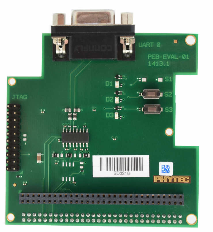
효율적인 debug에는 여러 terminal을 사용합니다. 연결과 build를 마친 뒤 이전에 build한 program directory에서 debug server를 시작합니다.
host$ west debugserverWest가 J-Link를 통해 target에 연결하고 debug server를 열린 상태로 유지합니다. 다른 terminal에서 GDB를 시작해 target에 연결합니다.
host$ gdb-multiarch build/zephyr/zephyr.elf -tui
(gdb) targ rem :2331
Remote debugging using :2331
0x1ffe0008 in _vector_table ()
(gdb) mon halt
(gdb) mon reset
(gdb) c
Continuing.
이후 표준 GDB 기법으로 program을 debug할 수 있습니다.
Source
출처
영어 원문에는 문단, 문서 지시문, 표, 코드, 코드 심벌, 경로를 그대로 보존했습니다.