Part 1
요약·해설
IT82XX2 EVB의 hardware, connector wiring과 Windows·Ubuntu flashing을 설명합니다.
RISC-V RV32IMAFC
256KB SRAM · 512/1024KB flash
USB-to-UART
Part 2
접을 수 있는 영어 원문 전체
영어 원문 전체 펼치기
0C7627CE6618B5D2847A367F30E3FD94DC1283876971597FE22CD9E3409A6FAF
.. _it82xx2_evb:

ITE IT82XX2 series
######################

Overview
********

The IT82XX2 is a 32-bit RISC-V microcontroller.
And a highly integrated embedded controller with system functions.
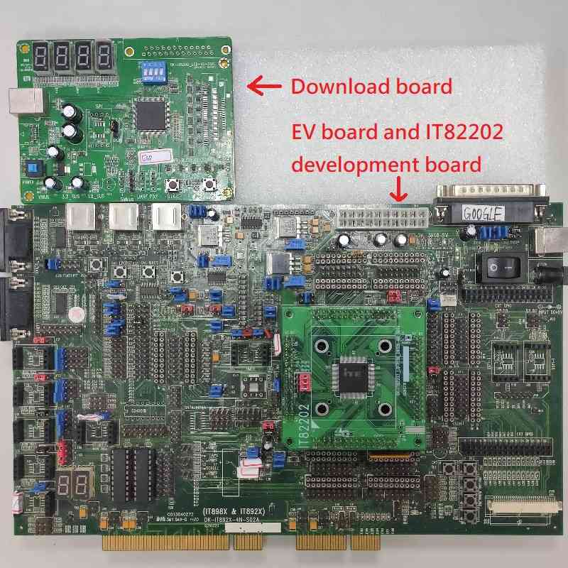
It is suitable for mobile system applications. The picture below is
the IT82202 development board (also known as it82xx2_evb) and its debug card.

.. figure:: ../../../../../../../boards/ite/it82xx2_evb/doc/it82xx2_evb_and_debug_card.jpg
     :align: center
     :alt: IT82202 EVB

To find out more about ITE, visit our World Wide Web at:`ITE's website`_

Hardware
********
The IT82XX2 series contains different chip types(ex, it82202, it82302),
and they support different hardware features.
Listing the IT82202 hardware features as following:

- RISC-V RV32IMAFC instruction set
- 4KB instruction cache size
- 256KB SRAM in total
- Built-in 32.768 kHz clock generator
- Embedded Flash, 512K/1024K-byte e-flash
- eSPI, SSPI, SPI slave, BRAM, KBC, PECI, UART
- GPIO, PWM, ADC, INTC, WUC, Timer, Watchdog, KB scan, JTAG
- Support 6 Voltage Comparator
- Support Cryptographic Engine
- 6 SMBus channels, with 6 DMA controller, compatible with I2C
- USB 2.0 Full-speed Controller
- USB Type-c CC Logic
- USB Power Delivery


Supported Features
==================
currently supports the following hardware features:

.. list-table:: Supported Features
   :header-rows: 1
   :widths: auto

   * - Interface
     - Controller
     - Driver/Component
   * - NVIC
     - on-chip
     - interrupt controller
   * - FLASH
     - on-chip
     - flash controller
   * - PINCTRL
     - on-chip
     - pin controller
   * - ESPI
     - on-chip
     - espi
   * - PECI
     - on-chip
     - peci
   * - UART
     - on-chip
     - serial
   * - GPIO
     - on-chip
     - gpio
   * - PWM
     - on-chip
     - pwm
   * - ADC
     - on-chip
     - adc
   * - TIMER
     - on-chip
     - timer
   * - WATCHDOG
     - on-chip
     - watchdog
   * - KSCAN
     - on-chip
     - kscan
   * - SENSOR
     - on-chip
     - voltage comparator
   * - I2C
     - on-chip
     - i2c


Other hardware features are not currently supported by Zephyr.

The default configuration can be found in the
:zephyr_file:`boards/ite/it82xx2_evb/it82xx2_evb_defconfig` Kconfig file.

Programming and debugging on it82202
************************************

In order to upload the application to the device,
you'll need our flash tool and Download board.
You can get them at: `ITE's website`_.

Wiring
=======
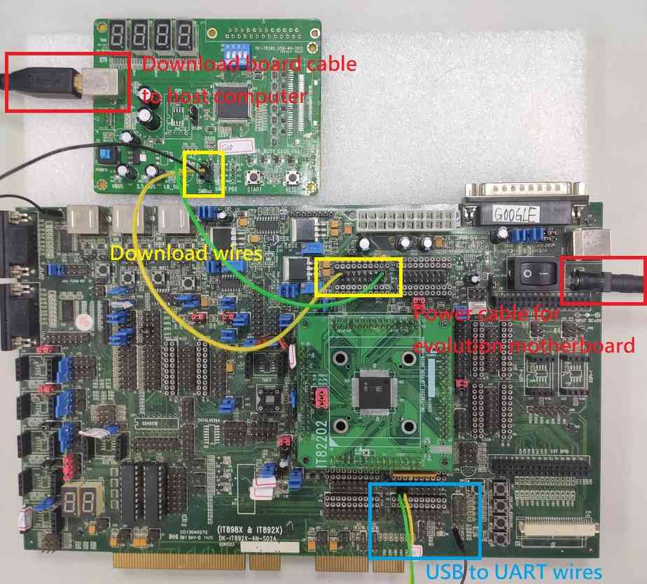
#. Connect the Download Board to your host computer using the USB cable.

#. Connect the it82xx2_evb to the evolution motherboard.

#. Connect the Download Board J5 to J41 on the evolution motherboard.

#. Connect the USB to UART wire to J33 on the evolution motherboard.

   .. image:: ../../../../../../../boards/ite/it82xx2_evb/doc/it82xx2_evb_wiring.jpg
        :align: center
        :alt: it82xx2_evb wiring

   .. note:: Be careful during connection!
    Use separate wires to connect I2C pins with pins on the it82xx2_evb board.
    Wiring connection is described in the table below.

    +-------------+---------------+
    |   J5        | it82xx2_evb   |
    |   Connector | J41 Connector |
    +=============+===============+
    |      2      |      E0       |
    +-------------+---------------+
    |      3      |      E7       |
    +-------------+---------------+
    |      4      |      GND      |
    +-------------+---------------+

    For USB to UART cable, connect the evolution motherboard as below:

    +-------------+---------------+
    | USB to UART | Evolution     |
    | cable       | motherboard   |
    |             | J33 Connector |
    +=============+===============+
    |     RX      |      B0       |
    +-------------+---------------+
    |     TX      |      B1       |
    +-------------+---------------+
    |     GND     |      GND      |
    +-------------+---------------+

Building
========

#. Build :ref:`hello_world` application as you would normally do
   (see :`Zephyr Getting Started Guide`_):.

   .. zephyr-app-commands::
      :board: it82xx2_evb
      :zephyr-app: samples/hello_world
      :goals: build

#. The file :file:`zephyr.bin` will be created by west.

Flashing
========

Windows
--------

Use the winflash tool to program a zephyr application
to the it82xx2 board flash.

#. Open the winflash tool and make sure the order you open the switch is right.
   First, turn on the Download board switch.
   Second, turn on the it82xx2_evb board switch.
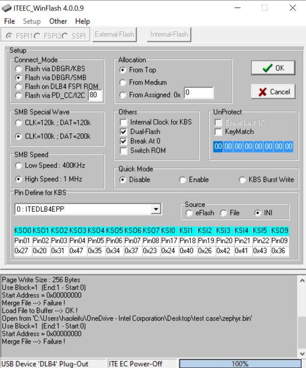
   Then, configure your winflash tool like below.

    .. figure:: ../../../../../../../boards/ite/it82xx2_evb/doc/WinFlashTool_P2.jpg
          :align: center

    .. figure:: ../../../../../../../boards/ite/it82xx2_evb/doc/WinFlashTool_P4.jpg

#. Using the winflash tool flash ``zephyr.bin`` into your ITE board.
   First, click the ``Load`` button and select your ``zephyr.bin`` file.
   Second, click ``run`` to flash the image into board.

    .. figure:: ../../../../../../../boards/ite/it82xx2_evb/doc/WinFlashTool_P3.jpg
          :align: center

#. At this point, you have flashed your image into ITE board and
   it will work if you turn on the ITE board. You can use a terminal program
   to verify flashing worked correctly.

   For example, open device manager to find the USB Serial Port(COM4) and use your
   terminal program to connect it(Speed: 115200).

    .. figure:: ../../../../../../../boards/ite/it82xx2_evb/doc/WinFlashTool_P1.jpg
          :align: center

#. Turn on the it82xx2_evb board switch, you should see ``"Hello World! it82xx2_evb"``
   sent by the board. If you don't see this message, press the Reset button and the
   message should appear.

Ubuntu
--------

#. Run your favorite terminal program to listen for output.
   Under Linux the terminal should be :code:`/dev/ttyUSB0`. Do not close it.

   For example:

   .. code-block:: console

      $ minicom -D /dev/ttyUSB0 -b 115200

#. Open a second terminal window and use the Linux flash tool to flash your board.

   .. code-block:: console

      $ sudo ~/itetool/ite -f build/zephyr/zephyr.bin

   .. note:: The source code of ITE tool can be downloaded here:
    https://www.ite.com.tw/uploads/product_download/itedlb4-linux-v106.tar.bz2

#. Split first and second terminal windows to view both of them.
   You should see ``"Hello World! it82xx2_evb"`` in the first terminal window.
   If you don't see this message, press the Reset button and the message should appear.

Debugging
=========

it82xx2_evb board can be debugged by connecting USB to UART. We can write commands and
read messages through minicom in the Ubuntu terminal.

Troubleshooting
===============

#. If the flash tool reports a failure, re-plug the 8390 Download board or
   power cycle the it82xx2_evb board and try again.

References
==========

.. target-notes::

.. _ITE's website: https://www.ite.com.tw/zh-tw/product/view?mid=169
.. _Zephyr Getting Started Guide: https://docs.zephyrproject.org/latest/getting_started/index.html
Part 3
한국어 전문 번역
개요
IT82XX2는 32-bit RISC-V microcontroller이자 system function을 통합한 embedded controller로 mobile system application에 적합합니다. 아래는 it82xx2_evb라고도 부르는 IT82202 development board와 debug card입니다.
ITE의 자세한 정보와 flash tool·Download board는 ITE product website에서 확인할 수 있습니다.
Hardware
IT82XX2 series에는 IT82202·IT82302 같은 여러 chip type이 있고 지원 hardware가 서로 다릅니다. IT82202의 기능은 다음과 같습니다.
- RISC-V RV32IMAFC instruction set
- 4KB instruction cache
- 총 256KB SRAM
- Built-in 32.768kHz clock generator
- Embedded Flash: 512KB/1024KB e-flash
- eSPI, SSPI, SPI slave, BRAM, KBC, PECI와 UART
- GPIO, PWM, ADC, INTC, WUC, timer, watchdog, keyboard scan과 JTAG
- Voltage comparator 6개
- Cryptographic engine
- I2C-compatible SMBus channel 6개와 DMA controller 6개
- USB 2.0 Full-Speed controller
- USB Type-C CC logic
- USB Power Delivery
Zephyr 지원 기능
| Interface | Controller | Driver/Component |
|---|---|---|
| NVIC | on-chip | interrupt controller |
| FLASH | on-chip | flash controller |
| PINCTRL | on-chip | pin controller |
| ESPI | on-chip | espi |
| PECI | on-chip | peci |
| UART | on-chip | serial |
| GPIO | on-chip | gpio |
| PWM | on-chip | pwm |
| ADC | on-chip | adc |
| TIMER | on-chip | timer |
| WATCHDOG | on-chip | watchdog |
| KSCAN | on-chip | kscan |
| SENSOR | on-chip | voltage comparator |
| I2C | on-chip | i2c |
그 밖의 hardware는 현재 Zephyr가 지원하지 않습니다. Default configuration은 boards/ite/it82xx2_evb/it82xx2_evb_defconfig에 있습니다.
IT82202 programming과 debugging
Wiring
- USB cable로 Download Board를 host computer에 연결합니다.
it82xx2_evb를 evolution motherboard에 연결합니다.- Download Board J5를 evolution motherboard J41에 연결합니다.
- USB-to-UART wire를 evolution motherboard J33에 연결합니다.
| J5 connector | it82xx2_evb J41 connector |
|---|---|
| 2 | E0 |
| 3 | E7 |
| 4 | GND |
USB-to-UART cable은 다음과 같이 evolution motherboard에 연결합니다.
| USB-to-UART cable | Evolution motherboard J33 connector |
|---|---|
| RX | B0 |
| TX | B1 |
| GND | GND |
Build
hello_world application을 일반적인 Zephyr 방식으로 build합니다.
west build -b it82xx2_evb samples/hello_worldWest가 zephyr.bin을 생성합니다.
Flashing
Windows
WinFlash tool로 Zephyr application을 it82xx2_evb board flash에 programming합니다.
- WinFlash를 열고 switch를 올바른 순서로 켭니다. 먼저 Download board switch, 다음으로 it82xx2_evb board switch를 켠 뒤 아래와 같이 WinFlash를 구성합니다.
it82xx2_evb WinFlash configuration page 2 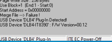
it82xx2_evb WinFlash configuration page 4 - Load를 click해
zephyr.bin을 선택하고 run을 click해 image를 board에 flash합니다.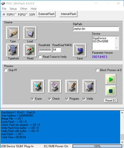
it82xx2_evb WinFlash load and run - Flash가 끝난 뒤 ITE board를 켭니다. Terminal program으로 결과를 검증할 수 있습니다. Windows Device Manager에서 USB Serial Port(COM4)를 찾아 speed
115200으로 연결합니다.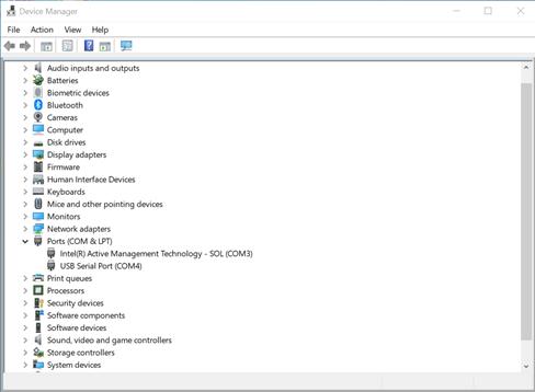
it82xx2_evb serial terminal - Board switch를 켜면
Hello World! it82xx2_evb가 보여야 합니다. 보이지 않으면 Reset button을 누릅니다.
Ubuntu
- Terminal program으로 출력을 수신합니다. Linux terminal device는
/dev/ttyUSB0이며 이 window를 닫지 않습니다.$ minicom -D /dev/ttyUSB0 -b 115200 - 두 번째 terminal window를 열고 Linux flash tool로 board를 flash합니다.
$ sudo ~/itetool/ite -f build/zephyr/zephyr.binITE tool source는 itedlb4-linux-v106.tar.bz2에서 받을 수 있습니다.
- 두 terminal window를 나란히 놓고 첫 번째 window에서
Hello World! it82xx2_evb를 확인합니다. 보이지 않으면 Reset button을 누릅니다.
Debugging
USB-to-UART를 연결해 Ubuntu terminal의 minicom으로 command를 쓰고 message를 읽을 수 있습니다.
Troubleshooting
Flash tool이 failure를 보고하면 8390 Download board를 다시 연결하거나 it82xx2_evb의 전원을 껐다 켠 뒤 다시 시도합니다.
참고 자료
Source
출처
영어 원문에는 문단, 문서 지시문, 표, 코드, 코드 심벌, 경로를 그대로 보존했습니다.