Part 1
요약·해설
BT610은 nRF52840, QSPI flash, magnetic sensor와 3개 terminal block을 결합해 analog/current, thermistor, digital, I2C와 SPI sensor를 연결합니다.
nRF52840 Cortex-M4F
4 analog · 4 thermistor · 2 digital
I2C · 2×SPI · UART
Part 2
접을 수 있는 영어 원문 전체
영어 원문 전체 펼치기
059D86AD901AC841DFFCD1E174B0759B1D5ABBDC23BB8B92BE709B0E0028257F
.. _bt610:

Ezurio Sentrius BT610 Sensor
############################

Overview
********

The Sentrius™ BT610 Sensor is a battery powered, Bluetooth v5 Long Range
integrated sensor platform that uses a Nordic Semiconductor nRF52840 ARM
Cortex-M4F CPU.

The sensor has the following features:

* :abbr:`ADC (Analog to Digital Converter)`
* CLOCK
* FLASH
* :abbr:`GPIO (General Purpose Input Output)`
* :abbr:`I2C (Inter-Integrated Circuit)`
* :abbr:`MPU (Memory Protection Unit)`
* :abbr:`NVIC (Nested Vectored Interrupt Controller)`
* :abbr:`PWM (Pulse Width Modulation)`
* :abbr:`QSPI (Quad Serial Peripheral Interface)`
* RADIO (Bluetooth Low Energy and 802.15.4)
* :abbr:`RTC (nRF RTC System Clock)`
* Segger RTT (RTT Console)
* :abbr:`SPI (Serial Peripheral Interface)`
* :abbr:`UART (Universal Asynchronous Receiver-Transmitter)`
* :abbr:`WDT (Watchdog Timer)`

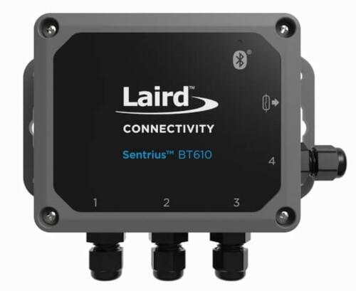
.. figure:: ../../../../../../../boards/ezurio/bt610/doc/img/bt610_front.jpg
     :align: center
     :alt: Sentrius BT610 Sensor, front view

     Sentrius BT610 Sensor, front view

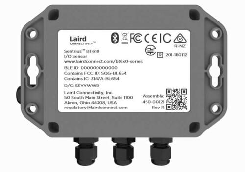
.. figure:: ../../../../../../../boards/ezurio/bt610/doc/img/bt610_back.jpg
     :align: center
     :alt: Sentrius BT610 Sensor, rear view

     Sentrius BT610 Sensor, rear view

More information about the board can be found at the
`Sentrius BT610 website`_.

Hardware
********

Supported Features
==================

The BT610 Sensor supports the following
hardware features:

+-----------+------------+----------------------+
| Interface | Controller | Driver/Component     |
+===========+============+======================+
| ADC       | on-chip    | adc                  |
+-----------+------------+----------------------+
| CLOCK     | on-chip    | clock_control        |
+-----------+------------+----------------------+
| FLASH     | on-chip    | flash                |
+-----------+------------+----------------------+
| GPIO      | on-chip    | gpio                 |
+-----------+------------+----------------------+
| I2C(M)    | on-chip    | i2c                  |
+-----------+------------+----------------------+
| MPU       | on-chip    | arch/arm             |
+-----------+------------+----------------------+
| NVIC      | on-chip    | arch/arm             |
+-----------+------------+----------------------+
| PWM       | on-chip    | pwm                  |
+-----------+------------+----------------------+
| QSPI      | on-chip    | qspi                 |
+-----------+------------+----------------------+
| RADIO     | on-chip    | Bluetooth,           |
|           |            | ieee802154           |
+-----------+------------+----------------------+
| RTC       | on-chip    | system clock         |
+-----------+------------+----------------------+
| RTT       | Segger     | console              |
+-----------+------------+----------------------+
| SPI(M)    | on-chip    | spi                  |
+-----------+------------+----------------------+
| UART      | on-chip    | serial               |
+-----------+------------+----------------------+
| WDT       | on-chip    | watchdog             |
+-----------+------------+----------------------+

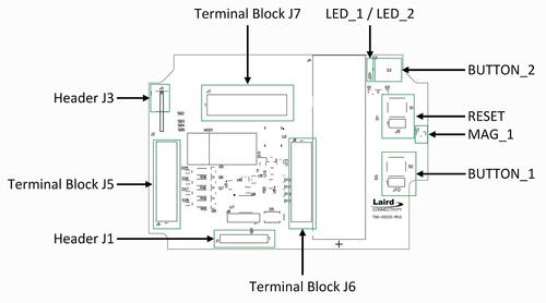
.. figure:: ../../../../../../../boards/ezurio/bt610/doc/img/bt610_board.jpg
     :align: center
     :alt: Sentrius BT610 Sensor, board layout

     Sentrius BT610 Sensor, board layout

Connections and IOs
===================

LED
---

Two LEDs are visible through the BT610 housing lid. Note that the LEDs can be
driven either directly, or via PWM. PWM should be used when current consumption
is required to be minimised.

* LED_1 (red) = LED0 = P1.07 (Red LED 1)
* LED_2 (green) = LED1 = P1.03 (Green LED 2)

* LED_PWM_1 (red) = LED0PWM = P1.07 (Red PWM LED 1)
* LED_PWM_2 (green) = LED1PWM = P1.03 (Green PWM LED 2)

Push button
------------

The BT610 incorporates three mechanical push buttons. Note these are only
accessible with the housing cover removed.

Two of the buttons are available for use via the board DTS file, as follows.

* BUTTON_1 = SW0 = P0.24 (Boot button SW1)
* BUTTON_2 = SW1 = P1.01 (Tamper switch SW2)

A third mechanical push button is provided to allow reset of the on-board
microcontroller.

Magnetoresistive sensor
-----------------------

The BT610 incorporates a Honeywell SM351LT magnetoresistive sensor. Refer to
the `Honeywell SM351LT datasheet`_ for further details.

* MAG_1 = SW2 = P1.15 (SM3531LT_0)

External flash memory
---------------------

A 64Mbit external flash memory part is available for storage of application
images and data. Refer to the `Macronix MX25R6435FZNIL0 datasheet`_ for further
details.

The flash memory is connected to the on-board QSPI device controller.

* MX25R64 = QSPI

Voltage reference
-----------------

A precision 2.5V voltage reference is provided on the V_REF input for use
during AD measurements.

This can deliver up to 50mA peak and 20mA continuous current.


Sensor connectivity
-------------------

The BT610 incorporates three terminal blocks J5, J6 & J7 that allow
connectivity to its sensor inputs, as follows.

Terminal Block J5
-----------------

+-----------+------------------------+----------------------------+-----------+
| Pin No.   | Name                   | Description                | Direction |
+===========+========================+============================+===========+
| 1         | EXT_SPI_CS_2           | External SPI CS 2          | OUT       |
+-----------+------------------------+----------------------------+-----------+
| 2         | GND                    | GND                        | (N/A)     |
+-----------+------------------------+----------------------------+-----------+
| 3         | AIN4                   | Analog Input 4             | IN        |
+-----------+------------------------+----------------------------+-----------+
| 4         | AIN3                   | Analog Input 3             | IN        |
+-----------+------------------------+----------------------------+-----------+
| 5         | GND                    | GND                        | (N/A)     |
+-----------+------------------------+----------------------------+-----------+
| 6         | AIN2                   | Analog Input 2             | IN        |
+-----------+------------------------+----------------------------+-----------+
| 7         | AIN1                   | Analog Input 1             | IN        |
+-----------+------------------------+----------------------------+-----------+
| 8         | GND                    | GND                        | (N/A)     |
+-----------+------------------------+----------------------------+-----------+
| 9         | DIN2                   | Digital Input 2            | IN        |
+-----------+------------------------+----------------------------+-----------+
| 10        | DO2                    | Digital Output 2           | OUT       |
+-----------+------------------------+----------------------------+-----------+

Terminal Block J6
-----------------

+-----------+------------------------+----------------------------+-----------+
| Pin No.   | Name                   | Description                | Direction |
+===========+========================+============================+===========+
| 1         | DO1                    | Digital Output 1           | OUT       |
+-----------+------------------------+----------------------------+-----------+
| 2         | DIN1                   | Digital Input 1            | IN        |
+-----------+------------------------+----------------------------+-----------+
| 3         | GND                    | GND                        | (N/A)     |
+-----------+------------------------+----------------------------+-----------+
| 4         | THERM4                 | Thermistor Input 4         | IN        |
+-----------+------------------------+----------------------------+-----------+
| 5         | THERM3                 | Thermistor Input 3         | IN        |
+-----------+------------------------+----------------------------+-----------+
| 6         | GND                    | GND                        | (N/A)     |
+-----------+------------------------+----------------------------+-----------+
| 7         | THERM2                 | Thermistor Input 2         | IN        |
+-----------+------------------------+----------------------------+-----------+
| 8         | THERM1                 | Thermistor Input 1         | IN        |
+-----------+------------------------+----------------------------+-----------+
| 9         | GND                    | GND                        | (N/A)     |
+-----------+------------------------+----------------------------+-----------+
| 10        | B+ OUT                 | Ext. sensor power supply   | (N/A)     |
+-----------+------------------------+----------------------------+-----------+

Terminal Block J7
-----------------

+-----------+------------------------+----------------------------+-----------+
| Pin No.   | Name                   | Description                | Direction |
+===========+========================+============================+===========+
| 1         | UART_1_RTS             | UART 1 RTS                 | IN        |
+-----------+------------------------+----------------------------+-----------+
| 2         | UART_1_CTS             | UART 1 CTS                 | OUT       |
+-----------+------------------------+----------------------------+-----------+
| 3         | UART_1_RXD             | UART 1 RXD                 | IN        |
+-----------+------------------------+----------------------------+-----------+
| 4         | UART_1_TXD             | UART 1 TXD                 | OUT       |
+-----------+------------------------+----------------------------+-----------+
| 5         | EXT_I2C_SCL            | External I2C SCL           | OUT       |
+-----------+------------------------+----------------------------+-----------+
| 6         | EXT_I2C_SDA            | External I2C SDA           | IN/OUT    |
+-----------+------------------------+----------------------------+-----------+
| 7         | EXT_SPI_CLK/TRACEDATA3 | Ext. SPI CLK/TRACE DATA 3  | OUT       |
+-----------+------------------------+----------------------------+-----------+
| 8         | EXT_SPI_MISO           | External SPI MISO          | IN        |
+-----------+------------------------+----------------------------+-----------+
| 9         | EXT_SPI_MOSI           | External SPI MOSI          | OUT       |
+-----------+------------------------+----------------------------+-----------+
| 10        | EXT_SPI_CS_1           | External SPI CS 1          | OUT       |
+-----------+------------------------+----------------------------+-----------+

Analog inputs
-------------

The four external Analog Inputs are multiplexed to a single host
microcontroller AD input, AIN_1, via a TI TMUX1204 multiplexer.

Refer to the `TI TMUX1204 datasheet`_ for further details.

Signals up to 12V, to a maximum of 50mA, can be applied to the external Analog
Inputs.

External Analog Input connections are made to the multiplexer as follows.

+--------------+--------------+
| Input        | MUX Input    |
+==============+==============+
| AIN1         | S1           |
+--------------+--------------+
| AIN2         | S2           |
+--------------+--------------+
| AIN3         | S3           |
+--------------+--------------+
| AIN4         | S4           |
+--------------+--------------+

A TI TCA9538 port expander is used to determine the mode of each Analog Input,
for either voltage or current measurement, and also to control the mutliplexer.
A high level applied to the appropriate expander port pin enables the
associated analog input as a current input; when a low logic level is applied,
voltage measurement mode is selected.

Refer to the `TI TCA9538 datasheet`_ for further details.

The expander port connections are as follows.

+--------------+---------------+
| Pin          | Function      |
+==============+===============+
| P0           | AIN1 mode     |
+--------------+---------------+
| P1           | AIN2 mode     |
+--------------+---------------+
| P2           | AIN3 mode     |
+--------------+---------------+
| P3           | AIN4 mode     |
+--------------+---------------+
| P4           | MUX A0        |
+--------------+---------------+
| P5           | MUX A1        |
+--------------+---------------+
| P6           | (N/C)         |
+--------------+---------------+
| P7           | (N/C)         |
+--------------+---------------+

The following illustrates some possible configuration values for the port
expander. Note that it is possible for combinations of voltage and current
measurement to be applied such that some external Analog Inputs measure current
and others voltage. This is not shown below.

+----------------+------------------------------+
| Expander value | Selected Analog Input & mode |
+================+==============================+
| b'00000000'    | AIN1, voltage measurement    |
+----------------+------------------------------+
| b'00000001'    | AIN1, current measurement    |
+----------------+------------------------------+
| b'00010000'    | AIN2, voltage measurement    |
+----------------+------------------------------+
| b'00010010'    | AIN2, current measurement    |
+----------------+------------------------------+
| b'00100000'    | AIN3, voltage measurement    |
+----------------+------------------------------+
| b'00100100'    | AIN3, current measurement    |
+----------------+------------------------------+
| b'00110000'    | AIN4, voltage measurement    |
+----------------+------------------------------+
| b'00111000'    | AIN4, current measurement    |
+----------------+------------------------------+

Circuitry associated with the analog input measurements can be disabled when
not in use.

A GPIO is used to control this behaviour, as shown below.

+----------------+-----------+
| ANALOG_ENABLE  | Behaviour |
+================+===========+
| 0              | Disabled  |
+----------------+-----------+
| 1              | Enabled   |
+----------------+-----------+

Thermistor inputs
-----------------

The four external thermistor inputs are connected to a single AD input, AIN_2,
via a TI TMUX1204 multiplexer.

Refer to the `TI TMUX1204 datasheet`_ for further details.

External analog input connections are made to the multiplexer as follows.

+--------------+--------------+
| Input        | MUX Input    |
+==============+==============+
| THERM1       | S1           |
+--------------+--------------+
| THERM2       | S2           |
+--------------+--------------+
| THERM3       | S3           |
+--------------+--------------+
| THERM4       | S4           |
+--------------+--------------+

The same port expander used to select external analog inputs is also used to
select external thermistor inputs.

The table below defines possible values that can be written.

+----------------+-----------------------+
| Expander value | Selected Analog Input |
+================+=======================+
| b'00000000'    | THERM1                |
+----------------+-----------------------+
| b'00010000'    | THERM2                |
+----------------+-----------------------+
| b'00100000'    | THERM3                |
+----------------+-----------------------+
| b'00110000'    | THERM4                |
+----------------+-----------------------+

A GPIO line is used to enable electronics associated with thermistor
measurement. This is controlled as shown below.

+----------------+-----------------------+
| THERM_ENABLE   | Behaviour             |
+================+=======================+
| 0              | Enabled               |
+----------------+-----------------------+
| 1              | Disabled              |
+----------------+-----------------------+

Note the thermistor circuit must be calibrated before use. A suggested method
for achieving this is described in the
`BT610 Zephyr Application Thermistor Calibration`_ application note.

Digital inputs
--------------

Two external digital inputs are available for connection to external signals.
For the digital level being applied to be detected, an appropriate output pin
must first be set. This approach is taken to ensure supporting circuitry can be
powered down when the input state is not being determined. When in use, the
external digital input level can be read from the appropriate input pin.

The output and input pins required are as follows.

+----------------+----------------+
| Enable Pin     | Input Read Pin |
+================+================+
| DIN_1_ENABLE   | DIN_1          |
+----------------+----------------+
| DIN_2_ENABLE   | DIN_2          |
+----------------+----------------+

Digital outputs
---------------

Two external digital outputs are available to provide signals to or to directly
drive external equipment.

To provide a high level on the external digital output, a high logic level is
applied to the appropriate host microcontroller output.

The output pins required are as follows.

+----------------+--------------------------+
| Output Pin     | External Sensor Terminal |
+================+==========================+
| DO_1_MCU       | DO1                      |
+----------------+--------------------------+
| DO_2_MCU       | DO2                      |
+----------------+--------------------------+

External power supply
---------------------

Power can be supplied to external sensors via the B+ OUT terminal. This is
enabled by setting the BATTERY_OUTPUT_ENABLE GPIO line. In addition, the
external supply can be boosted to 5V by setting the HIGH_SUPPLY_ENABLE GPIO
line. When 5V is not selected, the external power supply follows the
battery voltage.

Up to 50mA peak and 20mA continuous current can be delivered by the External
Power Supply.

External sensor I2C port
------------------------

External I2C sensors can be connected on the external I2C port. Note that
external I2C sensors should be powered from the B+ terminal to ensure applied
voltage levels match those expected internally by the board.

Required pins are as follows.

+-------------+--------------------------+
| Output Pin  | External Sensor Terminal |
+=============+==========================+
| SCL_PIN     | EXT_I2C_SCL              |
+-------------+--------------------------+
| SDA_PIN     | EXT_I2C_SDA              |
+-------------+--------------------------+


External sensor SPI port
------------------------

Up to 2 external SPI sensors can be connected on the external SPI port. Note
that external SPI sensors should be powered from the B+ terminal to ensure
applied voltage levels match those expected internally by the board.

Required pins are as follows.

+-------------+--------------------------+
| Output Pin  | External Sensor Terminal |
+=============+==========================+
| SCK_PIN     | EXT_I2C_SCL              |
+-------------+--------------------------+
| MOSI_PIN    | EXT_I2C_SDA              |
+-------------+--------------------------+
| MISO_PIN    | EXT_SPI_MISO             |
+-------------+--------------------------+
| SDA_PIN     | EXT_I2C_SDA              |
+-------------+--------------------------+
| CS_GPIOS    | EXT_I2C_SDA              |
+-------------+--------------------------+
| CS_GPIOS    | EXT_I2C_SDA              |
+-------------+--------------------------+


Programming and Debugging
*************************

Applications for the ``bt610`` board configuration can be
built and flashed in the usual way (see :ref:`build_an_application`
and :ref:`application_run` for more details); however, the standard
debugging targets are not currently available.

The BT610 features a 10 way header, J3, for connection of a
programmer/debugger, with pinout as follows.

+-----------+------------+----------------------+
| Pin No.   | Name       | Description          |
+===========+============+======================+
| 1         | 3.3V       | Power Supply, 3.3V   |
+-----------+------------+----------------------+
| 2         | SWDIO      | Data Input/Output    |
+-----------+------------+----------------------+
| 3         | GND        | GND                  |
+-----------+------------+----------------------+
| 4         | SWDCLK     | Clock Pin            |
+-----------+------------+----------------------+
| 5         | GND        | GND                  |
+-----------+------------+----------------------+
| 6         | SWO        | Trace Output Pin     |
+-----------+------------+----------------------+
| 7         | (N/C)      | Not Connected        |
+-----------+------------+----------------------+
| 8         | (N/C)      | Not Connected        |
+-----------+------------+----------------------+
| 9         | GND        | GND                  |
+-----------+------------+----------------------+
| 10        | nRESET     | Reset Pin            |
+-----------+------------+----------------------+

Access to the sensor debug UART is facilitated by a 6 pin header, J1, with
pinout as follows.

+-----------+------------+----------------------+-----------+
| Pin No.   | Name       | Description          | Direction |
+===========+============+======================+===========+
| 1         | GND        | GND                  | N/A       |
+-----------+------------+----------------------+-----------+
| 2         | UART_0_RTS | UART 0 RTS Pin       | IN        |
+-----------+------------+----------------------+-----------+
| 3         | 3.3V       | Power Supply, 3.3V   | N/A       |
+-----------+------------+----------------------+-----------+
| 4         | UART_0_RX  | UART 0 RX Pin        | IN        |
+-----------+------------+----------------------+-----------+
| 5         | UART_0_TX  | UART 0 TX Pin        | OUT       |
+-----------+------------+----------------------+-----------+
| 6         | UART_0_CTS | UART 0 CTS Pin       | OUT       |
+-----------+------------+----------------------+-----------+

Note that pin 3 requires a solder bridge to be closed to enable powering of the
BT610 board via the UART connector.

Flashing
========

Follow the instructions in the :ref:`nordic_segger` page to install
and configure all the necessary software. Further information can be
found in :ref:`nordic_segger_flashing`. Then build and flash
applications as usual (see :ref:`build_an_application` and
:ref:`application_run` for more details).

Here is an example for the :ref:`hello_world` application.

First, run your favorite terminal program to listen for output.

NOTE: On the BT610, the UART lines are at TTL levels and must be passed through
an appropriate line driver circuit for translation to RS232 levels. Refer to
the `MAX3232 datasheet`_ for a suitable driver IC.

.. code-block:: console

   $ minicom -D <tty_device> -b 115200

Replace :code:`<tty_device>` with the port where the BT610 can be found. For
example, under Linux, :code:`/dev/ttyUSB0`.

Then build and flash the application in the usual way.

.. zephyr-app-commands::
   :zephyr-app: samples/hello_world
   :board: bt610
   :goals: build flash

Note that an external debugger is required to perform application flashing.

Debugging
=========

The ``bt610`` board does not have an on-board J-Link debug IC
as some nRF5x development boards, however, instructions from the
:ref:`nordic_segger` page also apply to this board, with the additional step
of connecting an external debugger.

Testing Bluetooth on the BT610
***********************************
Many of the Bluetooth examples will work on the BT610.
Try them out:

* :ref:`ble_peripheral`
* :ref:`bluetooth-eddystone-sample`
* :ref:`bluetooth-ibeacon-sample`


Testing the LEDs and buttons on the BT610
*****************************************

There are 2 samples that allow you to test that the buttons (switches) and LEDs
on the board are working properly with Zephyr:

* :zephyr:code-sample:`blinky`
* :zephyr:code-sample:`button`

You can build and flash the examples to make sure Zephyr is running correctly
on your board. The button, LED and sensor device definitions can be found in
:zephyr_file:`boards/ezurio/bt610/bt610.dts`.


References
**********

.. target-notes::

.. _Sentrius BT610 website: https://www.ezurio.com/iot-devices/iot-sensors/sentrius-bt610-io-sensor
.. _Honeywell SM351LT datasheet: https://sensing.honeywell.com/honeywell-sensing-nanopower-series-datasheet-50095501-c-en.pdf
.. _MAX3232 datasheet: https://www.ti.com/lit/ds/symlink/max3232.pdf
.. _TI TMUX1204 datasheet: https://www.ti.com/lit/gpn/TMUX1204
.. _TI TCA9538 datasheet: https://www.ti.com/lit/gpn/TCA9538
.. _Macronix MX25R6435FZNIL0 datasheet: https://www.macronix.com/Lists/Datasheet/Attachments/7913/MX25R6435F,%20Wide%20Range,%2064Mb,%20v1.5.pdf
.. _BT610 Zephyr Application Thermistor Calibration: https://www.ezurio.com/technology/bt610-thermistor-coefficient-calculator
Part 3
한국어 전문 번역
개요
Sentrius BT610 Sensor는 Nordic Semiconductor nRF52840 ARM Cortex-M4F CPU를 사용하는 battery-powered Bluetooth v5 Long Range integrated sensor platform입니다.
이 sensor에는 다음 기능이 있습니다.
- ADC(Analog-to-Digital Converter)
- CLOCK
- FLASH
- GPIO(General Purpose Input/Output)
- I2C(Inter-Integrated Circuit)
- MPU(Memory Protection Unit)
- NVIC(Nested Vectored Interrupt Controller)
- PWM(Pulse Width Modulation)
- QSPI(Quad Serial Peripheral Interface)
- RADIO(Bluetooth Low Energy와 802.15.4)
- RTC(nRF RTC System Clock)
- Segger RTT(RTT Console)
- SPI(Serial Peripheral Interface)
- UART(Universal Asynchronous Receiver-Transmitter)
- WDT(Watchdog Timer)
Board에 관한 자세한 정보는 Sentrius BT610 website에서 확인할 수 있습니다.
Hardware
지원 기능
BT610 Sensor는 다음 hardware 기능을 지원합니다.
| Interface | Controller | Driver/Component |
|---|---|---|
| ADC | on-chip | adc |
| CLOCK | on-chip | clock_control |
| FLASH | on-chip | flash |
| GPIO | on-chip | gpio |
| I2C(M) | on-chip | i2c |
| MPU | on-chip | arch/arm |
| NVIC | on-chip | arch/arm |
| PWM | on-chip | pwm |
| QSPI | on-chip | qspi |
| RADIO | on-chip | Bluetooth, ieee802154 |
| RTC | on-chip | system clock |
| RTT | Segger | console |
| SPI(M) | on-chip | spi |
| UART | on-chip | serial |
| WDT | on-chip | watchdog |
연결과 I/O
LED
BT610 housing lid를 통해 LED 두 개를 볼 수 있습니다. LED는 직접 또는 PWM으로 구동할 수 있으며, current consumption을 최소화해야 할 때는 PWM을 사용해야 합니다.
- LED_1(red) = LED0 = P1.07(Red LED 1)
- LED_2(green) = LED1 = P1.03(Green LED 2)
- LED_PWM_1(red) = LED0PWM = P1.07(Red PWM LED 1)
- LED_PWM_2(green) = LED1PWM = P1.03(Green PWM LED 2)
Push button
BT610에는 mechanical push button 세 개가 있으며 housing cover를 제거해야 접근할 수 있습니다.
그중 두 button은 board DTS file을 통해 다음과 같이 사용할 수 있습니다.
- BUTTON_1 = SW0 = P0.24(Boot button SW1)
- BUTTON_2 = SW1 = P1.01(Tamper switch SW2)
세 번째 mechanical push button은 onboard microcontroller를 reset하기 위해 제공됩니다.
Magnetoresistive sensor
BT610에는 Honeywell SM351LT magnetoresistive sensor가 탑재됩니다. 자세한 내용은 Honeywell SM351LT datasheet를 참조하십시오.
- MAG_1 = SW2 = P1.15(SM3531LT_0)
External flash memory
Application image와 data 저장을 위한 64Mbit external flash memory가 있습니다. 자세한 내용은 Macronix MX25R6435FZNIL0 datasheet를 참조하십시오.
Flash memory는 onboard QSPI device controller에 연결됩니다.
- MX25R64 = QSPI
Voltage reference
AD measurement에 사용하도록 V_REF input에 precision 2.5V voltage reference가 제공됩니다.
최대 50mA peak, 20mA continuous current를 공급할 수 있습니다.
Sensor 연결
BT610에는 sensor input 연결용 terminal block J5, J6, J7 세 개가 다음과 같이 제공됩니다.
Terminal Block J5
| Pin No. | Name | Description | Direction |
|---|---|---|---|
| 1 | EXT_SPI_CS_2 | External SPI CS 2 | OUT |
| 2 | GND | GND | (N/A) |
| 3 | AIN4 | Analog Input 4 | IN |
| 4 | AIN3 | Analog Input 3 | IN |
| 5 | GND | GND | (N/A) |
| 6 | AIN2 | Analog Input 2 | IN |
| 7 | AIN1 | Analog Input 1 | IN |
| 8 | GND | GND | (N/A) |
| 9 | DIN2 | Digital Input 2 | IN |
| 10 | DO2 | Digital Output 2 | OUT |
Terminal Block J6
| Pin No. | Name | Description | Direction |
|---|---|---|---|
| 1 | DO1 | Digital Output 1 | OUT |
| 2 | DIN1 | Digital Input 1 | IN |
| 3 | GND | GND | (N/A) |
| 4 | THERM4 | Thermistor Input 4 | IN |
| 5 | THERM3 | Thermistor Input 3 | IN |
| 6 | GND | GND | (N/A) |
| 7 | THERM2 | Thermistor Input 2 | IN |
| 8 | THERM1 | Thermistor Input 1 | IN |
| 9 | GND | GND | (N/A) |
| 10 | B+ OUT | Ext. sensor power supply | (N/A) |
Terminal Block J7
| Pin No. | Name | Description | Direction |
|---|---|---|---|
| 1 | UART_1_RTS | UART 1 RTS | IN |
| 2 | UART_1_CTS | UART 1 CTS | OUT |
| 3 | UART_1_RXD | UART 1 RXD | IN |
| 4 | UART_1_TXD | UART 1 TXD | OUT |
| 5 | EXT_I2C_SCL | External I2C SCL | OUT |
| 6 | EXT_I2C_SDA | External I2C SDA | IN/OUT |
| 7 | EXT_SPI_CLK/TRACEDATA3 | Ext. SPI CLK/TRACE DATA 3 | OUT |
| 8 | EXT_SPI_MISO | External SPI MISO | IN |
| 9 | EXT_SPI_MOSI | External SPI MOSI | OUT |
| 10 | EXT_SPI_CS_1 | External SPI CS 1 | OUT |
Analog input
External analog input 네 개는 TI TMUX1204 multiplexer를 통해 host microcontroller의 단일 AD input AIN_1로 multiplex됩니다.
자세한 내용은 TI TMUX1204 datasheet를 참조하십시오.
External analog input에는 최대 50mA에서 최대 12V signal을 인가할 수 있습니다.
External analog input은 다음과 같이 multiplexer에 연결됩니다.
| Input | MUX Input |
|---|---|
| AIN1 | S1 |
| AIN2 | S2 |
| AIN3 | S3 |
| AIN4 | S4 |
TI TCA9538 port expander는 각 analog input의 voltage 또는 current measurement mode를 결정하고 multiplexer도 제어합니다. 해당 expander port pin에 high level을 인가하면 연관된 analog input이 current input으로 활성화되고, low logic level을 인가하면 voltage measurement mode가 선택됩니다.
자세한 내용은 TI TCA9538 datasheet를 참조하십시오.
Expander port 연결은 다음과 같습니다.
| Pin | Function |
|---|---|
| P0 | AIN1 mode |
| P1 | AIN2 mode |
| P2 | AIN3 mode |
| P3 | AIN4 mode |
| P4 | MUX A0 |
| P5 | MUX A1 |
| P6 | (N/C) |
| P7 | (N/C) |
다음 표는 port expander에 설정할 수 있는 값의 예입니다. 일부 external analog input은 current를, 다른 input은 voltage를 측정하도록 조합할 수도 있지만 아래 표에는 표시하지 않았습니다.
| Expander value | Selected Analog Input & mode |
|---|---|
| b'00000000' | AIN1, voltage measurement |
| b'00000001' | AIN1, current measurement |
| b'00010000' | AIN2, voltage measurement |
| b'00010010' | AIN2, current measurement |
| b'00100000' | AIN3, voltage measurement |
| b'00100100' | AIN3, current measurement |
| b'00110000' | AIN4, voltage measurement |
| b'00111000' | AIN4, current measurement |
Analog input measurement 관련 circuit은 사용하지 않을 때 비활성화할 수 있습니다.
이 동작은 GPIO로 다음과 같이 제어합니다.
| ANALOG_ENABLE | Behaviour |
|---|---|
| 0 | Disabled |
| 1 | Enabled |
Thermistor input
External thermistor input 네 개는 TI TMUX1204 multiplexer를 통해 단일 AD input AIN_2에 연결됩니다.
자세한 내용은 TI TMUX1204 datasheet를 참조하십시오.
External thermistor input은 다음과 같이 multiplexer에 연결됩니다.
| Input | MUX Input |
|---|---|
| THERM1 | S1 |
| THERM2 | S2 |
| THERM3 | S3 |
| THERM4 | S4 |
External analog input 선택에 사용한 동일한 port expander가 external thermistor input 선택에도 사용됩니다.
다음 표는 기록할 수 있는 값을 정의합니다.
| Expander value | Selected Analog Input |
|---|---|
| b'00000000' | THERM1 |
| b'00010000' | THERM2 |
| b'00100000' | THERM3 |
| b'00110000' | THERM4 |
GPIO line은 thermistor measurement 관련 electronics를 활성화하는 데 사용되며 다음과 같이 제어됩니다.
| THERM_ENABLE | Behaviour |
|---|---|
| 0 | Enabled |
| 1 | Disabled |
Digital input
External signal 연결용 digital input 두 개를 제공합니다. 인가된 digital level을 검출하려면 먼저 알맞은 output pin을 설정해야 합니다. 이 방식은 input state를 확인하지 않을 때 supporting circuit의 전원을 끌 수 있도록 하기 위한 것입니다. 사용할 때는 알맞은 input pin에서 external digital input level을 읽을 수 있습니다.
필요한 output pin과 input pin은 다음과 같습니다.
| Enable Pin | Input Read Pin |
|---|---|
| DIN_1_ENABLE | DIN_1 |
| DIN_2_ENABLE | DIN_2 |
Digital output
External equipment에 signal을 제공하거나 직접 구동하기 위한 external digital output 두 개를 제공합니다.
External digital output에 high level을 제공하려면 알맞은 host microcontroller output에 high logic level을 인가합니다.
필요한 output pin은 다음과 같습니다.
| Output Pin | External Sensor Terminal |
|---|---|
| DO_1_MCU | DO1 |
| DO_2_MCU | DO2 |
External power supply
B+ OUT terminal을 통해 external sensor에 전원을 공급할 수 있습니다. BATTERY_OUTPUT_ENABLE GPIO line을 설정하면 활성화됩니다. 또한 HIGH_SUPPLY_ENABLE GPIO line을 설정하면 external supply를 5V로 boost할 수 있습니다. 5V를 선택하지 않으면 external power supply는 battery voltage를 따릅니다.
External power supply는 최대 50mA peak, 20mA continuous current를 공급할 수 있습니다.
External sensor I2C port
External I2C sensor를 external I2C port에 연결할 수 있습니다. Board 내부에서 예상하는 voltage level과 인가 level을 맞추려면 external I2C sensor에 B+ terminal의 전원을 공급해야 합니다.
필요한 pin은 다음과 같습니다.
| Output Pin | External Sensor Terminal |
|---|---|
| SCL_PIN | EXT_I2C_SCL |
| SDA_PIN | EXT_I2C_SDA |
External sensor SPI port
External SPI sensor를 최대 두 개까지 external SPI port에 연결할 수 있습니다. Board 내부에서 예상하는 voltage level과 인가 level을 맞추려면 external SPI sensor에 B+ terminal의 전원을 공급해야 합니다.
필요한 pin은 원문 표와 같습니다.
| Output Pin | External Sensor Terminal |
|---|---|
| SCK_PIN | EXT_I2C_SCL |
| MOSI_PIN | EXT_I2C_SDA |
| MISO_PIN | EXT_SPI_MISO |
| SDA_PIN | EXT_I2C_SDA |
| CS_GPIOS | EXT_I2C_SDA |
| CS_GPIOS | EXT_I2C_SDA |
Programming과 Debugging
bt610 board configuration용 application은 일반적인 방법으로 build하고 flash할 수 있지만, 표준 debugging target은 현재 사용할 수 없습니다.
BT610에는 programmer/debugger 연결용 10-way header J3가 있으며 pinout은 다음과 같습니다.
| Pin No. | Name | Description |
|---|---|---|
| 1 | 3.3V | Power Supply, 3.3V |
| 2 | SWDIO | Data Input/Output |
| 3 | GND | GND |
| 4 | SWDCLK | Clock Pin |
| 5 | GND | GND |
| 6 | SWO | Trace Output Pin |
| 7 | (N/C) | Not Connected |
| 8 | (N/C) | Not Connected |
| 9 | GND | GND |
| 10 | nRESET | Reset Pin |
Sensor debug UART는 다음 pinout의 6-pin header J1을 통해 접근할 수 있습니다.
| Pin No. | Name | Description | Direction |
|---|---|---|---|
| 1 | GND | GND | N/A |
| 2 | UART_0_RTS | UART 0 RTS Pin | IN |
| 3 | 3.3V | Power Supply, 3.3V | N/A |
| 4 | UART_0_RX | UART 0 RX Pin | IN |
| 5 | UART_0_TX | UART 0 TX Pin | OUT |
| 6 | UART_0_CTS | UART 0 CTS Pin | OUT |
Flashing
Nordic Segger 안내에 따라 필요한 software를 설치하고 구성합니다. Nordic Segger flashing 안내를 확인한 뒤 일반적인 절차로 application을 build하고 flash합니다.
다음은 hello_world application 예입니다.
먼저 선호하는 terminal program을 실행해 output을 수신합니다.
$ minicom -D <tty_device> -b 115200<tty_device>를 BT610이 연결된 port로 바꿉니다. Linux 예시는 /dev/ttyUSB0입니다.
그다음 일반적인 방법으로 application을 build하고 flash합니다.
west build -b bt610 samples/hello_world
west flash
Application flashing을 수행하려면 external debugger가 필요합니다.
Debugging
bt610 board에는 일부 nRF5x development board와 달리 onboard J-Link debug IC가 없습니다. 그러나 external debugger를 연결하는 단계를 추가하면 Nordic Segger 안내를 이 board에도 적용할 수 있습니다.
BT610에서 Bluetooth 시험
많은 Bluetooth example이 BT610에서 동작합니다. 다음 sample을 시험해 보십시오.
- Bluetooth LE peripheral
- Bluetooth Eddystone
- Bluetooth iBeacon
BT610 LED와 button 시험
Board의 button(switch)과 LED가 Zephyr에서 올바르게 동작하는지 시험할 수 있는 sample은 두 개입니다.
blinkybutton
Example을 build·flash하여 board에서 Zephyr가 올바르게 실행되는지 확인할 수 있습니다. Button, LED와 sensor device 정의는 boards/ezurio/bt610/bt610.dts에 있습니다.
참고 자료
Source
출처
영어 원문에는 문단, 문서 지시문, 표, 코드, 코드 심벌, 경로를 그대로 보존했습니다.