Part 1
요약·해설
BT510은 nRF52840, magnetoresistive sensor, accelerometer와 temperature sensor를 IP67 housing에 통합한 device입니다.
nRF52840 Cortex-M4F
SM351LT · LIS2DH · Si7055
Custom 10-way TagConnect
Part 2
접을 수 있는 영어 원문 전체
영어 원문 전체 펼치기
A304EFE1A5866660DCD875F11C91D91BFA71290863AE0A6156808DF2FCF6EC3D
.. _bt510:

Ezurio Sentrius BT510 Sensor
############################

Overview
********

The Sentrius™ BT510 Sensor is a battery powered, Bluetooth v5 Long Range integrated sensor that uses a Nordic Semiconductor nRF52840 ARM Cortex-M4F CPU.

The sensor has the following features:

* :abbr:`ADC (Analog to Digital Converter)`
* CLOCK
* FLASH
* :abbr:`GPIO (General Purpose Input Output)`
* :abbr:`I2C (Inter-Integrated Circuit)`
* :abbr:`MPU (Memory Protection Unit)`
* :abbr:`NVIC (Nested Vectored Interrupt Controller)`
* :abbr:`PWM (Pulse Width Modulation)`
* RADIO (Bluetooth Low Energy and 802.15.4)
* :abbr:`RTC (nRF RTC System Clock)`
* Segger RTT (RTT Console)
* :abbr:`UART (Universal Asynchronous Receiver-Transmitter)`
* :abbr:`WDT (Watchdog Timer)`

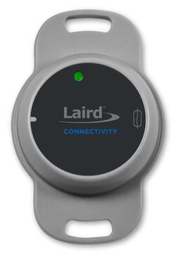
.. figure:: ../../../../../../../boards/ezurio/bt510/doc/img/bt510.jpg
     :align: center
     :alt: Sentrius BT510 Sensor, front view

     Sentrius BT510 Sensor, front view

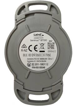
.. figure:: ../../../../../../../boards/ezurio/bt510/doc/img/bt510_back.jpg
     :align: center
     :alt: Sentrius BT510 Sensor, rear view

     Sentrius BT510 Sensor, rear view

More information about the board can be found at the
`Sentrius BT510 website`_.

Hardware
********

Supported Features
==================

The BT510 Sensor supports the following
hardware features:

+-----------+------------+----------------------+
| Interface | Controller | Driver/Component     |
+===========+============+======================+
| ADC       | on-chip    | adc                  |
+-----------+------------+----------------------+
| CLOCK     | on-chip    | clock_control        |
+-----------+------------+----------------------+
| FLASH     | on-chip    | flash                |
+-----------+------------+----------------------+
| GPIO      | on-chip    | gpio                 |
+-----------+------------+----------------------+
| I2C(M)    | on-chip    | i2c                  |
+-----------+------------+----------------------+
| MPU       | on-chip    | arch/arm             |
+-----------+------------+----------------------+
| NVIC      | on-chip    | arch/arm             |
+-----------+------------+----------------------+
| PWM       | on-chip    | pwm                  |
+-----------+------------+----------------------+
| RADIO     | on-chip    | Bluetooth,           |
|           |            | ieee802154           |
+-----------+------------+----------------------+
| RTC       | on-chip    | system clock         |
+-----------+------------+----------------------+
| RTT       | Segger     | console              |
+-----------+------------+----------------------+
| UART      | on-chip    | serial               |
+-----------+------------+----------------------+
| WDT       | on-chip    | watchdog             |
+-----------+------------+----------------------+

Connections and IOs
===================

LED
---

Two LEDs are visible through the BT510 housing lid.

* LED_1A (green) = P0.22
* LED_1B (red) = P0.20

Push button
------------

The BT510 housing lid also acts as a push button.

* BUTTON_1 = SW1 = P1.10

Magnetoresistive sensor
-----------------------

The BT510 incorporates a Honeywell SM351LT magnetoresistive sensor. Refer to the `Honeywell SM351LT datasheet`_ for further details.

* MAG = P1.14

Accelerometer
-------------

The BT510 incorporates an I2C ST Microelectronics LIS2DH accelerometer. Refer to the `ST Microelectronics LIS2DH datasheet`_ for further details.

* SDA = P0.26
* SCL = P0.27
* INT_1 = P1.05
* INT_2 = P1.12

Temperature Sensor
------------------

The BT510 incorporates an I2C Silabs SI7055 temperature sensor. Refer to the `Silabs 7055 datasheet`_ for further details.

* SDA = P0.26
* SCL = P0.27

Programming and Debugging
*************************

Applications for the ``bt510`` board configuration can be built, flashed, and
debugged in the usual way. See :ref:`build_an_application` and
:ref:`application_run` for more details on building and running.

The BT510 features a TagConnect 10 way socket for connection of a
programmer/debugger, refer to `TagConnect TC2050 product page`_
for details of an appropriate TagConnect cable.

A non-standard layout is used to include access to the sensor debug UART.

+-----------+------------+----------------------+
| Pin No.   | Name       | Description          |
+===========+============+======================+
| 1         | Vcc        | Power Supply, 3.3V   |
+-----------+------------+----------------------+
| 2         | SWDIO      | SWD Data             |
+-----------+------------+----------------------+
| 3         | RXD        | Debug UART RX Data   |
+-----------+------------+----------------------+
| 4         | SWDCLK     | SWD Clock            |
+-----------+------------+----------------------+
| 5         | TM         | Spare GPIO           |
+-----------+------------+----------------------+
| 6         | SWO        | SWD Output           |
+-----------+------------+----------------------+
| 7         | N/C        | Not Connected        |
+-----------+------------+----------------------+
| 8         | TXD        | Debug UART TX Data   |
+-----------+------------+----------------------+
| 9         | GND        | Ground               |
+-----------+------------+----------------------+
| 10        | RESET      | Reset, Active Low    |
+-----------+------------+----------------------+

Connectivity to the programmer/debugger must be modified to match
the pinout shown above.

Ezurio provide the USB-SWD programming board (750-03239) that supports
this connector layout, refer to the `USB SWD Programmer product page`_
.

Flashing
========

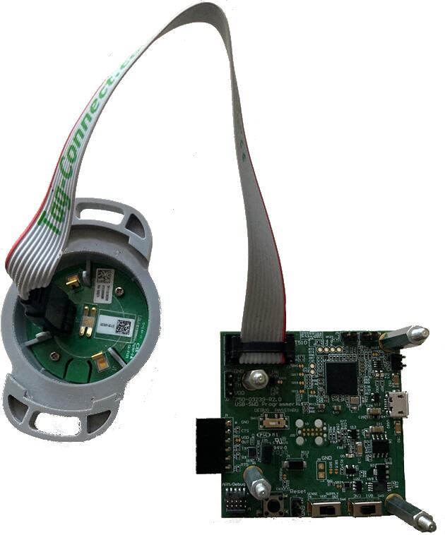
To connect the BT510 board for programming or debugging using the USB-SWD programming
board, on the programming board set SW6 to the supply out position and SW5 to the 3V3
position, ensure there is a jumper on J35 and that SW1 is in the debug position, then
connect the BT510 to the board using the Tag-Connect cable via J3:

.. figure:: ../../../../../../../boards/ezurio/bt510/doc/img/bt510_prog.jpg
     :align: center
     :alt: Sentrius BT510 Sensor connected to programming board

     Sentrius BT510 Sensor connected to programming board

Then build and flash applications as usual (see :ref:`build_an_application` and
:ref:`application_run` for more details). For example, to flash:

.. code-block:: console

   $ ninja flash

Here is an example for the :ref:`hello_world` application.

First, run your favorite terminal program to listen for output.

NOTE: On the BT510, the UART lines are at TTL levels and must be passed through
an appropriate line driver circuit for translation to RS232 levels. Refer to the `MAX3232 datasheet`_
for a suitable driver IC. The USB-SWD programming board has an in-built UART connected
to the BT510 acting as a USB CDC port, on Linux and Windows 10 this driver should be
installed automatically, for Windows 7, the MBED driver is required to use the serial
port - see the `MBED Serial Driver`_ link for details and how to install the driver.

.. code-block:: console

   $ minicom -D <tty_device> -b 115200

Replace :code:`<tty_device>` with the port where the bt510 can be found. For example, under Linux, :code:`/dev/ttyACM0`.

Then build and flash the application in the usual way.

.. zephyr-app-commands::
   :zephyr-app: samples/hello_world
   :board: bt510
   :goals: build flash

Note that an external debugger is required to perform application flashing.

Debugging
=========

The ``bt510`` board does not have an on-board J-Link debug IC
as some nRF5x development boards, however, instructions from the
:ref:`nordic_segger` page also apply to this board, with the additional step
of connecting an external debugger. The USB-SWD programmer board has a CMSIS debugger
compatible interface and debugging can be performed using pyocd, openocd or any other
applications that support the CMSIS interface.

Testing Bluetooth on the BT510
***********************************
Many of the Bluetooth examples will work on the BT510.
Try them out:

* :ref:`ble_peripheral`
* :ref:`bluetooth-eddystone-sample`
* :ref:`bluetooth-ibeacon-sample`


Testing the LEDs and buttons on the BT510
*****************************************

There are 2 samples that allow you to test that the buttons (switches) and LEDs on
the board are working properly with Zephyr:

* :zephyr:code-sample:`blinky`
* :zephyr:code-sample:`button`

You can build and flash the examples to make sure Zephyr is running correctly on
your board. The button, LED and sensor device definitions can be found in
:zephyr_file:`boards/ezurio/bt510/bt510.dts`.


References
**********

.. target-notes::

.. _Sentrius BT510 website: https://www.ezurio.com/iot-devices/iot-sensors/bt510-bluetooth-5-long-range-ip67-multi-sensor
.. _TagConnect TC2050 product page: https://www.tag-connect.com/product/tc2050-idc-050
.. _USB SWD Programmer product page: https://www.ezurio.com/wireless-modules/programming-kits/usb-swd-programming-kit
.. _MAX3232 datasheet: https://www.ti.com/lit/ds/symlink/max3232.pdf
.. _Silabs 7055 datasheet: https://www.silabs.com/documents/public/data-sheets/Si7050-1-3-4-5-A20.pdf
.. _ST Microelectronics LIS2DH datasheet: https://www.st.com/resource/en/datasheet/lis2dh.pdf
.. _Honeywell SM351LT datasheet: https://sensing.honeywell.com/honeywell-sensing-nanopower-series-datasheet-50095501-c-en.pdf
.. _MBED Serial Driver: https://os.mbed.com/docs/mbed-os/v6.8/program-setup/windows-serial-driver.html
Part 3
한국어 전문 번역
개요
Sentrius BT510 Sensor는 Nordic Semiconductor nRF52840 ARM Cortex-M4F CPU를 사용하는 battery-powered Bluetooth v5 Long Range integrated sensor입니다.
이 sensor에는 다음 기능이 있습니다.
- ADC(Analog-to-Digital Converter)
- CLOCK
- FLASH
- GPIO(General Purpose Input/Output)
- I2C(Inter-Integrated Circuit)
- MPU(Memory Protection Unit)
- NVIC(Nested Vectored Interrupt Controller)
- PWM(Pulse Width Modulation)
- RADIO(Bluetooth Low Energy와 802.15.4)
- RTC(nRF RTC System Clock)
- Segger RTT(RTT Console)
- UART(Universal Asynchronous Receiver-Transmitter)
- WDT(Watchdog Timer)
Board에 관한 자세한 정보는 Sentrius BT510 website에서 확인할 수 있습니다.
Hardware
지원 기능
BT510 Sensor는 다음 hardware 기능을 지원합니다.
| Interface | Controller | Driver/Component |
|---|---|---|
| ADC | on-chip | adc |
| CLOCK | on-chip | clock_control |
| FLASH | on-chip | flash |
| GPIO | on-chip | gpio |
| I2C(M) | on-chip | i2c |
| MPU | on-chip | arch/arm |
| NVIC | on-chip | arch/arm |
| PWM | on-chip | pwm |
| RADIO | on-chip | Bluetooth, ieee802154 |
| RTC | on-chip | system clock |
| RTT | Segger | console |
| UART | on-chip | serial |
| WDT | on-chip | watchdog |
연결과 I/O
LED
BT510 housing lid를 통해 LED 두 개를 볼 수 있습니다.
- LED_1A(green) = P0.22
- LED_1B(red) = P0.20
Push button
BT510 housing lid 자체도 push button으로 동작합니다.
- BUTTON_1 = SW1 = P1.10
Magnetoresistive sensor
BT510에는 Honeywell SM351LT magnetoresistive sensor가 탑재됩니다. 자세한 내용은 Honeywell SM351LT datasheet를 참조하십시오.
- MAG = P1.14
Accelerometer
BT510에는 I2C STMicroelectronics LIS2DH accelerometer가 탑재됩니다. 자세한 내용은 STMicroelectronics LIS2DH datasheet를 참조하십시오.
- SDA = P0.26
- SCL = P0.27
- INT_1 = P1.05
- INT_2 = P1.12
Temperature Sensor
BT510에는 I2C Silicon Labs Si7055 temperature sensor가 탑재됩니다. 자세한 내용은 Silabs 7055 datasheet를 참조하십시오.
- SDA = P0.26
- SCL = P0.27
Programming과 Debugging
bt510 board configuration용 application은 일반적인 방법으로 build, flash, debug할 수 있습니다. 자세한 build·run 방법은 Zephyr application build 및 run 안내를 참조하십시오.
BT510에는 programmer/debugger 연결용 TagConnect 10-way socket이 있습니다. 적절한 cable은 TagConnect TC2050 product page를 참조하십시오.
Sensor debug UART 접근까지 포함하기 위해 표준과 다른 pin layout을 사용합니다.
| Pin No. | Name | Description |
|---|---|---|
| 1 | Vcc | Power Supply, 3.3V |
| 2 | SWDIO | SWD Data |
| 3 | RXD | Debug UART RX Data |
| 4 | SWDCLK | SWD Clock |
| 5 | TM | Spare GPIO |
| 6 | SWO | SWD Output |
| 7 | N/C | Not Connected |
| 8 | TXD | Debug UART TX Data |
| 9 | GND | Ground |
| 10 | RESET | Reset, Active Low |
Programmer/debugger 연결은 위 pinout에 맞게 수정해야 합니다.
Ezurio는 이 connector layout을 지원하는 USB-SWD programming board(750-03239)를 제공합니다. USB SWD Programmer product page를 참조하십시오.
Flashing
USB-SWD programming board를 사용해 BT510을 programming/debugging하려면 programming board에서 SW6을 supply out 위치, SW5를 3V3 위치로 설정합니다. J35에 jumper가 있는지, SW1이 debug 위치인지 확인한 다음 J3를 통해 Tag-Connect cable로 BT510을 board에 연결합니다.
그다음 일반적인 방법으로 application을 build하고 flash합니다. Flash 예시는 다음과 같습니다.
$ ninja flash다음은 hello_world application 예입니다.
먼저 선호하는 terminal program을 실행해 output을 수신합니다.
$ minicom -D <tty_device> -b 115200<tty_device>를 BT510이 연결된 port로 바꿉니다. Linux 예시는 /dev/ttyACM0입니다.
그다음 일반적인 방법으로 application을 build하고 flash합니다.
west build -b bt510 samples/hello_world
west flash
Application flashing을 수행하려면 external debugger가 필요합니다.
Debugging
bt510 board에는 일부 nRF5x development board와 달리 onboard J-Link debug IC가 없습니다. 그러나 external debugger를 연결하는 단계를 추가하면 Nordic Segger 안내를 그대로 적용할 수 있습니다. USB-SWD programmer board는 CMSIS debugger-compatible interface를 제공하며 pyOCD, OpenOCD 또는 CMSIS interface를 지원하는 다른 application으로 debug할 수 있습니다.
BT510에서 Bluetooth 시험
많은 Bluetooth example이 BT510에서 동작합니다. 다음 sample을 시험해 보십시오.
- Bluetooth LE peripheral
- Bluetooth Eddystone
- Bluetooth iBeacon
BT510 LED와 button 시험
Board의 button(switch)과 LED가 Zephyr에서 올바르게 동작하는지 시험할 수 있는 sample은 두 개입니다.
blinkybutton
Example을 build·flash하여 board에서 Zephyr가 올바르게 실행되는지 확인할 수 있습니다. Button, LED와 sensor device 정의는 boards/ezurio/bt510/bt510.dts에 있습니다.
참고 자료
Source
출처
영어 원문에는 문단, 문서 지시문, 표, 코드, 코드 심벌, 경로를 그대로 보존했습니다.