Part 1
요약·해설
BL652 DVK는 nRF52832 기반 BL652 module을 평가하며 FTDI UART console, Segger debugging과 Arduino-compatible header를 제공합니다.
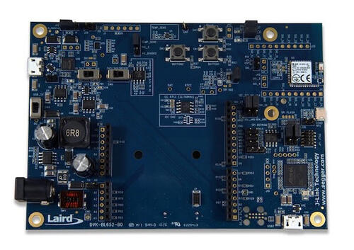
nRF52832 Cortex-M4F
Bluetooth LE
Arduino headers
Part 2
접을 수 있는 영어 원문 전체
영어 원문 전체 펼치기
EE29638CC673A73B5EB7B781C889A9B2E5C9FF64083FE31CD9A2A244BA5C4A99
.. _bl652_dvk:

Ezurio BL652 DVK
################

Overview
********

The BL652 Development Kit hardware provides
support for the Ezurio BL652 module powered by a Nordic Semiconductor nRF52832 ARM Cortex-M4F CPU.

This development kit has the following features:

* :abbr:`ADC (Analog to Digital Converter)`
* CLOCK
* FLASH
* :abbr:`GPIO (General Purpose Input Output)`
* :abbr:`I2C (Inter-Integrated Circuit)`
* :abbr:`MPU (Memory Protection Unit)`
* :abbr:`NVIC (Nested Vectored Interrupt Controller)`
* :abbr:`PWM (Pulse Width Modulation)`
* RADIO (Bluetooth Low Energy)
* :abbr:`RTC (nRF RTC System Clock)`
* Segger RTT (RTT Console)
* :abbr:`SPI (Serial Peripheral Interface)`
* :abbr:`UART (Universal asynchronous receiver-transmitter)`
* :abbr:`WDT (Watchdog Timer)`

Available BL652 DVK part numbers:

* DVK-BL652-SA
* DVK-BL652-SC

.. figure:: ../../../../../../../boards/ezurio/bl652_dvk/doc/img/bl652_dvk.jpg
     :align: center
     :alt: BL652 DVK

     BL652 DVK Board

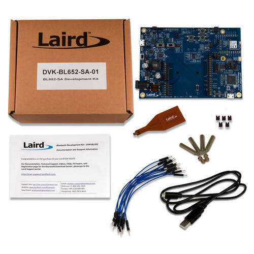
.. figure:: ../../../../../../../boards/ezurio/bl652_dvk/doc/img/BL652-SA_DVK_BoxContents.jpg
     :align: center
     :alt: BL652-SA DVK Box Contents

     BL652-SA DVK Box Contents

More information about the board can be found at the
`BL652 Module Website`_.

Hardware
********

Supported Features
==================

The BL652 DVK board configuration supports the following
hardware features:

+-----------+------------+----------------------+
| Interface | Controller | Driver/Component     |
+===========+============+======================+
| ADC       | on-chip    | adc                  |
+-----------+------------+----------------------+
| CLOCK     | on-chip    | clock_control        |
+-----------+------------+----------------------+
| FLASH     | on-chip    | flash                |
+-----------+------------+----------------------+
| GPIO      | on-chip    | gpio                 |
+-----------+------------+----------------------+
| I2C(M)    | on-chip    | i2c                  |
+-----------+------------+----------------------+
| MPU       | on-chip    | arch/arm             |
+-----------+------------+----------------------+
| NVIC      | on-chip    | arch/arm             |
+-----------+------------+----------------------+
| PWM       | on-chip    | pwm                  |
+-----------+------------+----------------------+
| RADIO     | on-chip    | Bluetooth            |
+-----------+------------+----------------------+
| RTC       | on-chip    | system clock         |
+-----------+------------+----------------------+
| RTT       | Segger     | console              |
+-----------+------------+----------------------+
| SPI(M/S)  | on-chip    | spi                  |
+-----------+------------+----------------------+
| UART      | on-chip    | serial               |
+-----------+------------+----------------------+
| WDT       | on-chip    | watchdog             |
+-----------+------------+----------------------+

Other hardware features have not been enabled yet for this board.
See `BL652 Module Website`_.

Connections and IOs
===================

LED
---

* LED1 (blue) = P0.17
* LED2 (blue) = P0.19

Push buttons
------------

* BUTTON1 = SW1 = P0.11
* BUTTON2 = SW2 = P0.15
* Reset = SW3 = boot/reset

External Connectors
-------------------

Arduino Headers
---------------

J33/J23 Power

+-------+--------------+-------------------------+
| PIN # | Signal Name  | NRF52832 Functions      |
+=======+==============+=========================+
| 1     | NC           | N/A                     |
+-------+--------------+-------------------------+
| 2     | IOREF (3v3)  | N/A                     |
+-------+--------------+-------------------------+
| 3     | RESET        | P0.21 / RESET           |
+-------+--------------+-------------------------+
| 4     | 3v3          | N/A                     |
+-------+--------------+-------------------------+
| 5     | 5V           | N/A                     |
+-------+--------------+-------------------------+
| 6     | GND          | N/A                     |
+-------+--------------+-------------------------+
| 7     | GND          | N/A                     |
+-------+--------------+-------------------------+
| 8     | VIN (12V)    | N/A                     |
+-------+--------------+-------------------------+

J31/J16 Analog in

+-------+--------------+-------------------------+
| PIN # | Signal Name  | NRF52832 Functions      |
+=======+==============+=========================+
| 1     | A0           | P0.03 / AIN1            |
+-------+--------------+-------------------------+
| 2     | A1           | P0.04 / AIN2            |
+-------+--------------+-------------------------+
| 3     | A2           | P0.28 / AIN4            |
+-------+--------------+-------------------------+
| 4     | A3           | P0.29 / AIN5            |
+-------+--------------+-------------------------+
| 5     | A4           | P0.30 / AIN6            |
+-------+--------------+-------------------------+
| 6     | A5           | P0.31 / AIN7            |
+-------+--------------+-------------------------+

J30/J15 Digital I/O

+-------+--------------+-------------------------+
| PIN # | Signal Name  | NRF52832 Functions      |
+=======+==============+=========================+
| 1     | D0 (RX)      | P0.11                   |
+-------+--------------+-------------------------+
| 2     | D1 (TX)      | P0.12                   |
+-------+--------------+-------------------------+
| 3     | D2           | P0.13                   |
+-------+--------------+-------------------------+
| 4     | D3           | P0.14 / TRACEDATA[3]    |
+-------+--------------+-------------------------+
| 5     | D4           | P0.15 / TRACEDATA[2]    |
+-------+--------------+-------------------------+
| 6     | D5           | P0.16 / TRACEDATA[1]    |
+-------+--------------+-------------------------+
| 7     | D6           | P0.17                   |
+-------+--------------+-------------------------+
| 8     | D7           | P0.18 / TRACEDATA[3]  / |
|       |              | SWO                     |
+-------+--------------+-------------------------+

J32/J22 Digital I/O

+-------+--------------+-------------------------+
| PIN # | Signal Name  | NRF52832 Functions      |
+=======+==============+=========================+
| 1     | D8           | P0.19                   |
+-------+--------------+-------------------------+
| 2     | D9           | P0.20 / TRACECLK        |
+-------+--------------+-------------------------+
| 3     | D10 (SS)     | P0.22                   |
+-------+--------------+-------------------------+
| 4     | D11 (MOSI)   | P0.23                   |
+-------+--------------+-------------------------+
| 5     | D12 (MISO)   | P0.24                   |
+-------+--------------+-------------------------+
| 6     | D13 (SCK)    | P0.25                   |
+-------+--------------+-------------------------+
| 7     | GND          | N/A                     |
+-------+--------------+-------------------------+
| 8     | AREF         | P0.02 / AIN0            |
+-------+--------------+-------------------------+
| 9     | SDA          | P0.26                   |
+-------+--------------+-------------------------+
| 10    | SCL          | P0.27                   |
+-------+--------------+-------------------------+


Programming and Debugging
*************************

Flashing
========

Follow the instructions in the :ref:`nordic_segger` page to install
and configure all the necessary software. Further information can be
found in :ref:`nordic_segger_flashing`. Then build and flash
applications as usual (see :ref:`build_an_application` and
:ref:`application_run` for more details).

Here is an example for the :ref:`hello_world` application.

First, run your favorite terminal program to listen for output.

NOTE: On the BL652 DVK, the FTDI USB should be used to access the UART console.

.. code-block:: console

   $ minicom -D <tty_device> -b 115200

Replace :code:`<tty_device>` with the port where the BL652 DVK
can be found. For example, under Linux, :code:`/dev/ttyUSB0`.

Then build and flash the application in the usual way.

.. zephyr-app-commands::
   :zephyr-app: samples/hello_world
   :board: bl652_dvk
   :goals: build flash

Debugging
=========

Refer to the :ref:`nordic_segger` page to learn about debugging Nordic based boards with a
Segger IC.

Testing Bluetooth on the BL652 DVK
**********************************
Many of the Bluetooth examples will work on the BL652 DVK.
Try them out:

* :ref:`ble_peripheral`
* :ref:`bluetooth-eddystone-sample`
* :ref:`bluetooth-ibeacon-sample`

Testing the LEDs and buttons in the BL652 DVK
*********************************************

There are 2 samples that allow you to test that the buttons (switches) and LEDs on
the board are working properly with Zephyr:

* :zephyr:code-sample:`blinky`
* :zephyr:code-sample:`button`

You can build and flash the examples to make sure Zephyr is running correctly on
your board. The button and LED definitions can be found in
:zephyr_file:`boards/ezurio/bl652_dvk/bl652_dvk.dts`.

References
**********

.. target-notes::

.. _BL652 Module Website: https://ezurio.com/wireless-modules/bluetooth-modules/bluetooth-5-modules/bl652-series-bluetooth-v5-nfc
Part 3
한국어 전문 번역
개요
BL652 Development Kit hardware는 Nordic Semiconductor nRF52832 ARM Cortex-M4F CPU 기반 Ezurio BL652 module을 지원합니다.
이 development kit에는 다음 기능이 있습니다.
- ADC(Analog-to-Digital Converter)
- CLOCK
- FLASH
- GPIO(General Purpose Input/Output)
- I2C(Inter-Integrated Circuit)
- MPU(Memory Protection Unit)
- NVIC(Nested Vectored Interrupt Controller)
- PWM(Pulse Width Modulation)
- RADIO(Bluetooth Low Energy)
- RTC(nRF RTC System Clock)
- Segger RTT(RTT Console)
- SPI(Serial Peripheral Interface)
- UART(Universal asynchronous receiver-transmitter)
- WDT(Watchdog Timer)
사용 가능한 BL652 DVK part number는 다음과 같습니다.
- DVK-BL652-SA
- DVK-BL652-SC
Board에 관한 자세한 정보는 BL652 Module Website에서 확인할 수 있습니다.
Hardware
지원 기능
BL652 DVK board configuration은 다음 hardware 기능을 지원합니다.
| Interface | Controller | Driver/Component |
|---|---|---|
| ADC | on-chip | adc |
| CLOCK | on-chip | clock_control |
| FLASH | on-chip | flash |
| GPIO | on-chip | gpio |
| I2C(M) | on-chip | i2c |
| MPU | on-chip | arch/arm |
| NVIC | on-chip | arch/arm |
| PWM | on-chip | pwm |
| RADIO | on-chip | Bluetooth |
| RTC | on-chip | system clock |
| RTT | Segger | console |
| SPI(M/S) | on-chip | spi |
| UART | on-chip | serial |
| WDT | on-chip | watchdog |
그 밖의 hardware 기능은 아직 이 board에서 활성화되지 않았습니다. BL652 Module Website를 참조하십시오.
연결과 I/O
LED
- LED1(blue) = P0.17
- LED2(blue) = P0.19
Push button
- BUTTON1 = SW1 = P0.11
- BUTTON2 = SW2 = P0.15
- Reset = SW3 = boot/reset
External Connector
Arduino Header
J33/J23 Power
| PIN # | Signal Name | NRF52832 Functions |
|---|---|---|
| 1 | NC | N/A |
| 2 | IOREF (3v3) | N/A |
| 3 | RESET | P0.21 / RESET |
| 4 | 3v3 | N/A |
| 5 | 5V | N/A |
| 6 | GND | N/A |
| 7 | GND | N/A |
| 8 | VIN (12V) | N/A |
J31/J16 Analog in
| PIN # | Signal Name | NRF52832 Functions |
|---|---|---|
| 1 | A0 | P0.03 / AIN1 |
| 2 | A1 | P0.04 / AIN2 |
| 3 | A2 | P0.28 / AIN4 |
| 4 | A3 | P0.29 / AIN5 |
| 5 | A4 | P0.30 / AIN6 |
| 6 | A5 | P0.31 / AIN7 |
J30/J15 Digital I/O
| PIN # | Signal Name | NRF52832 Functions |
|---|---|---|
| 1 | D0 (RX) | P0.11 |
| 2 | D1 (TX) | P0.12 |
| 3 | D2 | P0.13 |
| 4 | D3 | P0.14 / TRACEDATA[3] |
| 5 | D4 | P0.15 / TRACEDATA[2] |
| 6 | D5 | P0.16 / TRACEDATA[1] |
| 7 | D6 | P0.17 |
| 8 | D7 | P0.18 / TRACEDATA[3] / SWO |
J32/J22 Digital I/O
| PIN # | Signal Name | NRF52832 Functions |
|---|---|---|
| 1 | D8 | P0.19 |
| 2 | D9 | P0.20 / TRACECLK |
| 3 | D10 (SS) | P0.22 |
| 4 | D11 (MOSI) | P0.23 |
| 5 | D12 (MISO) | P0.24 |
| 6 | D13 (SCK) | P0.25 |
| 7 | GND | N/A |
| 8 | AREF | P0.02 / AIN0 |
| 9 | SDA | P0.26 |
| 10 | SCL | P0.27 |
Programming과 Debugging
Flashing
Nordic Segger 안내에 따라 필요한 software를 설치하고 구성합니다. 자세한 내용은 Nordic Segger flashing 안내를 참조하십시오. 그다음 일반적인 Zephyr application build·run 절차로 application을 build하고 flash할 수 있습니다.
다음은 hello_world application 예입니다.
먼저 선호하는 terminal program을 실행해 output을 수신합니다.
$ minicom -D <tty_device> -b 115200<tty_device>를 BL652 DVK가 연결된 port로 바꿉니다. Linux 예시는 /dev/ttyUSB0입니다.
그다음 일반적인 방법으로 application을 build하고 flash합니다.
west build -b bl652_dvk samples/hello_world
west flash
Debugging
Segger IC를 사용하는 Nordic 기반 board의 debugging 방법은 Nordic Segger 안내를 참조하십시오.
BL652 DVK에서 Bluetooth 시험
많은 Bluetooth example이 BL652 DVK에서 동작합니다. 다음 sample을 시험해 보십시오.
- Bluetooth LE peripheral
- Bluetooth Eddystone
- Bluetooth iBeacon
BL652 DVK LED와 button 시험
Board의 button(switch)과 LED가 Zephyr에서 올바르게 동작하는지 시험할 수 있는 sample은 두 개입니다.
blinkybutton
Example을 build·flash하여 board에서 Zephyr가 올바르게 실행되는지 확인할 수 있습니다. Button과 LED 정의는 boards/ezurio/bl652_dvk/bl652_dvk.dts에 있습니다.
참고 자료
Source
출처
영어 원문에는 문단, 문서 지시문, 표, 코드, 코드 심벌, 경로를 그대로 보존했습니다.