Part 1
요약·해설
BL5340 DVK는 128MHz application Cortex-M33F와 64MHz network Cortex-M33, rich external memory·sensor·display·Ethernet hardware를 결합합니다.
App 128MHz · Net 64MHz
Armv8-M · IDAU/SPU · TF-M
QSPI · Ethernet · TFT · sensors
Part 2
접을 수 있는 영어 원문 전체
영어 원문 전체 펼치기
DE16C789A871FD366C2523E37F4EAC9A3FFE6DE51FC2E868F912D69D6B04F4D0
.. _bl5340_dvk:

Ezurio BL5340 DVK
#################

Overview
********
The BL5340 Development Kit provides support for the Ezurio
BL5340 module which is powered by a dual-core Nordic Semiconductor
nRF5340 ARM Cortex-M33F CPU. The nRF5340 inside the BL5340 module is a
dual-core SoC based on the Arm® Cortex®-M33 architecture, with:

* a full-featured Arm Cortex-M33F core with DSP instructions, FPU, and
  Armv8-M Security Extension, running at up to 128 MHz, referred to as
  the **application core**
* a secondary Arm Cortex-M33 core, with a reduced feature set, running
  at a fixed 64 MHz, referred to as the **network core**.

The ``bl5340_dvk/nrf5340/cpuapp`` build target provides support for the application
core on the BL5340 module. The ``bl5340_dvk/nrf5340/cpunet`` build target provides
support for the network core on the BL5340 module. If ARM TrustZone is
used then the ``bl5340_dvk/nrf5340/cpuapp`` build target provides support for the
non-secure partition of the application core on the BL5340 module.

This development kit has the following features:

* :abbr:`ADC (Analog to Digital Converter)`
* CLOCK
* FLASH
* :abbr:`GPIO (General Purpose Input Output)`
* :abbr:`IDAU (Implementation Defined Attribution Unit)`
* :abbr:`I2C (Inter-Integrated Circuit)`
* :abbr:`I2S (Inter-Integrated Sound)`
* :abbr:`MPU (Memory Protection Unit)`
* :abbr:`NVIC (Nested Vectored Interrupt Controller)`
* :abbr:`PWM (Pulse Width Modulation)`
* :abbr:`QSPI (Quad Serial Peripheral Interface)`
* RADIO (Bluetooth Low Energy and 802.15.4)
* :abbr:`RTC (nRF RTC System Clock)`
* Segger RTT (RTT Console)
* :abbr:`SPI (Serial Peripheral Interface)`
* :abbr:`UARTE (Universal asynchronous receiver-transmitter)`
* :abbr:`USB (Universal Serial Bus)`
* :abbr:`WDT (Watchdog Timer)`

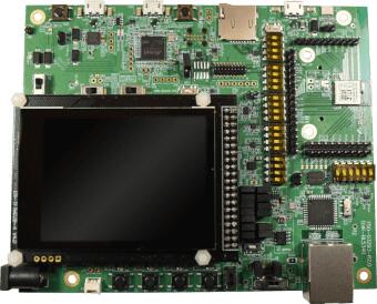
.. figure:: ../../../../../../../boards/ezurio/bl5340_dvk/doc/img/bl5340_dvk_top.jpg
     :align: center
     :alt: BL5340 DVK

     BL5340 DVK (Credit: Ezurio)

More information about the module can be found on the
`BL5340 homepage`_.

The `Nordic Semiconductor Infocenter`_
contains the processor's information and the datasheet.

Hardware
********

The BL5340 DVK has two external oscillators. The frequency of
the slow clock is 32.768KHz. The frequency of the main clock
is 32MHz.

Supported Features
==================

The ``bl5340_dvk/nrf5340/cpuapp`` board configuration supports the following
hardware features:

+-----------+------------+----------------------+
| Interface | Controller | Driver/Component     |
+===========+============+======================+
| ADC       | on-chip    | adc                  |
+-----------+------------+----------------------+
| CLOCK     | on-chip    | clock_control        |
+-----------+------------+----------------------+
| FLASH     | on-chip    | flash                |
+-----------+------------+----------------------+
| GPIO      | on-chip    | gpio                 |
+-----------+------------+----------------------+
| I2C(M)    | on-chip    | i2c                  |
+-----------+------------+----------------------+
| MPU       | on-chip    | arch/arm             |
+-----------+------------+----------------------+
| NVIC      | on-chip    | arch/arm             |
+-----------+------------+----------------------+
| QSPI(M)   | on-chip    | nor                  |
+-----------+------------+----------------------+
| PWM       | on-chip    | pwm                  |
+-----------+------------+----------------------+
| RTC       | on-chip    | system clock         |
+-----------+------------+----------------------+
| RTT       | Segger     | console              |
+-----------+------------+----------------------+
| SPI(M/S)  | on-chip    | spi                  |
+-----------+------------+----------------------+
| SPU       | on-chip    | system protection    |
+-----------+------------+----------------------+
| UARTE     | on-chip    | serial               |
+-----------+------------+----------------------+
| USB       | on-chip    | usb                  |
+-----------+------------+----------------------+
| WDT       | on-chip    | watchdog             |
+-----------+------------+----------------------+

The ``bl5340_dvk/nrf5340/cpunet`` board configuration supports the following
hardware features:

+-----------+------------+----------------------+
| Interface | Controller | Driver/Component     |
+===========+============+======================+
| CLOCK     | on-chip    | clock_control        |
+-----------+------------+----------------------+
| FLASH     | on-chip    | flash                |
+-----------+------------+----------------------+
| GPIO      | on-chip    | gpio                 |
+-----------+------------+----------------------+
| I2C(M)    | on-chip    | i2c                  |
+-----------+------------+----------------------+
| MPU       | on-chip    | arch/arm             |
+-----------+------------+----------------------+
| NVIC      | on-chip    | arch/arm             |
+-----------+------------+----------------------+
| RADIO     | on-chip    | Bluetooth,           |
|           |            | ieee802154           |
+-----------+------------+----------------------+
| RTC       | on-chip    | system clock         |
+-----------+------------+----------------------+
| RTT       | Segger     | console              |
+-----------+------------+----------------------+
| SPI(M/S)  | on-chip    | spi                  |
+-----------+------------+----------------------+
| UARTE     | on-chip    | serial               |
+-----------+------------+----------------------+
| WDT       | on-chip    | watchdog             |
+-----------+------------+----------------------+

Other hardware features have not been enabled yet for this board.
See `Nordic Semiconductor Infocenter`_
for a complete list of hardware features.

Connections and IOs
===================

An eight-pin GPIO port expander is used to provide additional inputs
and outputs to the BL5340 module.

Refer to the `TI TCA9538 datasheet`_ for further details.

LEDs
----

* LED1 (blue) = via TCA9538 port expander channel P4 (active low)
* LED2 (blue) = via TCA9538 port expander channel P5 (active low)
* LED3 (blue) = via TCA9538 port expander channel P6 (active low)
* LED4 (blue) = via TCA9538 port expander channel P7 (active low)

Push buttons
------------

* BUTTON1 = SW1 = via TCA9538 port expander channel P0 (active low)
* BUTTON2 = SW2 = via TCA9538 port expander channel P1 (active low)
* BUTTON3 = SW3 = via TCA9538 port expander channel P2 (active low)
* BUTTON4 = SW4 = via TCA9538 port expander channel P3 (active low)
* BOOT = boot (active low)

External Memory
===============

Several external memory sources are available for the BL5340 DVK. These
are described as follows.

Flash Memory
------------

A Macronix MX25R6435FZNIL0 8MB external QSPI Flash memory part is
incorporated for application image storage and large datasets.

Refer to the `Macronix MX25R6435FZNIL0 datasheet`_ for further details.

EEPROM Memory
-------------

A 32KB Giantec GT24C256C-2GLI-TR EEPROM is available via I2C for
storage of infrequently updated data and small datasets.

Refer to the `Giantec GT24C256C-2GLI-TR datasheet`_ for further details.

External Memory
---------------

An on-board micro SD card slot is available for use with micro SD cards.

Sensors
=======

The BL5340 DVK incorporates two sensors for user application testing.
These are described as follows.

Temperature, Pressure, Humidity & Air Quality Sensor
----------------------------------------------------

A Bosch BME680 Temperature, Pressure, Humidity & Air Quality sensor is
available via I2C for environmental measurement applications.

Refer to the `Bosch BME680 datasheet`_ for further details.

3-Axis Accelerometer
--------------------

An ST Microelectronics LIS3DH 3-Axis Accelerometer is available via I2C
for vibration and motion detection applications.

Refer to the `ST Microelectronics LIS3DH datasheet`_ for further details.

Ethernet
========

Cabled 10/100 Base-T Ethernet Connectivity is available via a Microchip
ENC424J600 Ethernet controller.

Refer to the `Microchip ENC424J600 datasheet`_ for further details.

TFT Display & Capacitive Touch Screen Controller
================================================

A 2.8 inch, 240 x 320 pixel TFT display with capacitive touch
controller is included with the BL5340 DVK for user interface
application features.

Refer to the `ER_TFTM028_4 datasheet`_ for a high level overview of the
display.

An ILI9341 TFT controller is incorporated in the TFT module and
acts as the main controller, controlled via SPI.

Refer to the `ILI9341 datasheet`_ for further details.

An FT6206 Capacitive Touch Controller, controlled via I2C is
also incorporated in the TFT module.

Refer to the `FT6206 datasheet`_ for further details.

Real-Time Clock
===============

A real-time clock is available for accurate time data availability.

Refer to the `Microchip MCP7940N datasheet`_ for further details.

DAC
===

A 10-bit Digital to Analog Converter is incorporated for generation of
variable voltages.

Refer to the `Microchip MCP4725 datasheet`_ for further details.

Security components
===================

- Implementation Defined Attribution Unit (`IDAU`_) on the application
  core. The IDAU is implemented with the System Protection Unit and is
  used to define secure and non-secure memory maps.  By default, all of
  the memory space (Flash, SRAM, and peripheral address space) is
  defined to be secure accessible only.
- Secure boot.

Programming and Debugging
*************************

The BL5340's application core supports the Armv8-M Security Extension.
Applications built for the ``bl5340_dvk/nrf5340/cpuapp`` board by default
boot in the Secure state.

The BL5340's network core does not support the Armv8-M Security
Extension. The IDAU may configure bus accesses by the network core to
have Secure attribute set; the latter allows to build and run Secure
only applications on the BL5340 module.

Building Secure/Non-Secure Zephyr applications with Arm |reg| TrustZone |reg|
=============================================================================

Applications on the BL5340 module may contain a Secure and a Non-Secure
firmware image for the application core. The Secure image can be built
using either Zephyr or `Trusted Firmware M`_ (TF-M). Non-Secure
firmware images are always built using Zephyr. The two alternatives are
described below.

.. note::

   By default the Secure image for BL5340's application core is
   built using TF-M.

Building the Secure firmware with TF-M
--------------------------------------

The process to build the Secure firmware image using TF-M and the
Non-Secure firmware image using Zephyr requires the following steps:

1. Build the Non-Secure Zephyr application
   for the application core using ``-DBOARD=bl5340_dvk/nrf5340/cpuapp/ns``.
   To invoke the building of TF-M the Zephyr build system requires the
   Kconfig option ``BUILD_WITH_TFM`` to be enabled, which is done by
   default when building Zephyr as a Non-Secure application.
   The Zephyr build system will perform the following steps automatically:

      * Build the Non-Secure firmware image as a regular Zephyr application
      * Build a TF-M (secure) firmware image
      * Merge the output image binaries together
      * Optionally build a bootloader image (MCUboot)

.. note::

   Depending on the TF-M configuration, an application DTS overlay may
   be required, to adjust the Non-Secure image Flash and SRAM starting
   address and sizes.

2. Build the application firmware for the network core using
   ``-DBOARD=bl5340_dvk/nrf5340/cpunet``.

Building the Secure firmware using Zephyr
-----------------------------------------

The process to build the Secure and the Non-Secure firmware images
using Zephyr requires the following steps:

1. Build the Secure Zephyr application for the application core
   using ``-DBOARD=bl5340_dvk/nrf5340/cpuapp`` and
   ``CONFIG_TRUSTED_EXECUTION_SECURE=y`` and ``CONFIG_BUILD_WITH_TFM=n``
   in the application project configuration file.
2. Build the Non-Secure Zephyr application for the application core
   using ``-DBOARD=bl5340_dvk/nrf5340/cpuapp/ns``.
3. Merge the two binaries together.
4. Build the application firmware for the network core using
   ``-DBOARD=bl5340_dvk/nrf5340/cpunet``.

When building a Secure/Non-Secure application for the BL5340's
application core, the Secure application will have to set the IDAU
(SPU) configuration to allow Non-Secure access to all CPU resources
utilized by the Non-Secure application firmware. SPU configuration
shall take place before jumping to the Non-Secure application.

Building a Secure only application
==================================

Build the Zephyr app in the usual way (see :ref:`build_an_application`
and :ref:`application_run`), using ``-DBOARD=bl5340_dvk/nrf5340/cpuapp`` for
the firmware running on the BL5340's application core, and using
``-DBOARD=bl5340_dvk/nrf5340/cpunet`` for the firmware running
on the BL5340's network core.

Flashing
========

Follow the instructions in the :ref:`nordic_segger` page to install
and configure all the necessary software. Further information can be
found in :ref:`nordic_segger_flashing`. Then you can build and flash
applications as usual (:ref:`build_an_application` and
:ref:`application_run` for more details).

.. warning::

   The BL5340 has a flash read-back protection feature. When flash
   read-back protection is active, you will need to recover the chip
   before reflashing. If you are flashing with
   :ref:`west <west-build-flash-debug>`, run this command for more
   details on the related ``--recover`` option:

   .. code-block:: console

      west flash -H -r nrfjprog --skip-rebuild

.. note::

   Flashing and debugging applications on the BL5340 DVK requires
   upgrading the nRF Command Line Tools to version 10.12.0 or newer.
   Further information on how to install the nRF Command Line Tools can
   be found in :ref:`nordic_segger_flashing`.

Here is an example for the :ref:`hello_world` application running on the
BL5340's application core.

First, run your favorite terminal program to listen for output.

.. code-block:: console

   $ minicom -D <tty_device> -b 115200

Replace :code:`<tty_device>` with the port where the BL5340 DVK board
can be found. For example, under Linux, :code:`/dev/ttyACM0`.

Then build and flash the application in the usual way.

.. zephyr-app-commands::
   :zephyr-app: samples/hello_world
   :board: bl5340_dvk/nrf5340/cpuapp
   :goals: build flash

Debugging
=========

Refer to the :ref:`nordic_segger` page to learn about debugging
boards with a Segger IC.

Testing Bluetooth on the BL5340 DVK
***********************************
Many of the Bluetooth examples will work on the BL5340 DVK.
Try them out:

* :ref:`ble_peripheral`
* :ref:`bluetooth-eddystone-sample`
* :ref:`bluetooth-ibeacon-sample`

References
**********

.. target-notes::

.. _IDAU:
   https://developer.arm.com/docs/100690/latest/attribution-units-sau-and-idau
.. _BL5340 homepage: https://www.ezurio.com/wireless-modules/bluetooth-modules/bluetooth-5-modules/bl5340-series-multi-core-bluetooth-52-802154-nfc-modules
.. _Nordic Semiconductor Infocenter: https://infocenter.nordicsemi.com
.. _TI TCA9538 datasheet: https://www.ti.com/lit/gpn/TCA9538
.. _Macronix MX25R6435FZNIL0 datasheet: https://www.macronix.com/Lists/Datasheet/Attachments/8868/MX25R6435F,%20Wide%20Range,%2064Mb,%20v1.6.pdf
.. _Giantec GT24C256C-2GLI-TR datasheet: https://www.giantec-semi.com/juchen1123/uploads/pdf/GT24C256C_DS_Cu.pdf
.. _Bosch BME680 datasheet: https://www.bosch-sensortec.com/media/boschsensortec/downloads/datasheets/bst-bme680-ds001.pdf
.. _ST Microelectronics LIS3DH datasheet: https://www.st.com/resource/en/datasheet/lis3dh.pdf
.. _Microchip ENC424J600 datasheet: https://ww1.microchip.com/downloads/en/DeviceDoc/39935c.pdf
.. _ER_TFTM028_4 datasheet: https://www.buydisplay.com/download/manual/ER-TFTM028-4_Datasheet.pdf
.. _ILI9341 datasheet: https://www.buydisplay.com/download/ic/ILI9341.pdf
.. _FT6206 datasheet: https://www.buydisplay.com/download/ic/FT6206.pdf
.. _Microchip MCP7940N datasheet: https://ww1.microchip.com/downloads/en/DeviceDoc/20005010H.pdf
.. _Microchip MCP4725 datasheet: https://ww1.microchip.com/downloads/en/DeviceDoc/22039d.pdf
.. _Trusted Firmware M: https://www.trustedfirmware.org/projects/tf-m/
Part 3
한국어 전문 번역
개요
BL5340 Development Kit는 dual-core Nordic Semiconductor nRF5340 ARM Cortex-M33F CPU 기반 Ezurio BL5340 module을 지원합니다. Module의 nRF5340은 Arm Cortex-M33 architecture 기반 dual-core SoC입니다.
- Application core: DSP instruction, FPU와 Armv8-M Security Extension을 갖춘 full-featured Cortex-M33F이며 최대 128MHz로 동작합니다.
- Network core: feature가 축소된 secondary Cortex-M33이며 fixed 64MHz로 동작합니다.
bl5340_dvk/nrf5340/cpuapp target은 application core를, bl5340_dvk/nrf5340/cpunet target은 network core를 지원합니다. ARM TrustZone을 사용하면 cpuapp target은 application core의 non-secure partition을 지원합니다.
이 development kit에는 다음 기능이 있습니다.
- ADC(Analog-to-Digital Converter)
- CLOCK
- FLASH
- GPIO(General Purpose Input/Output)
- IDAU(Implementation Defined Attribution Unit)
- I2C(Inter-Integrated Circuit)
- I2S(Inter-Integrated Sound)
- MPU(Memory Protection Unit)
- NVIC(Nested Vectored Interrupt Controller)
- PWM(Pulse Width Modulation)
- QSPI(Quad Serial Peripheral Interface)
- RADIO(Bluetooth Low Energy와 802.15.4)
- RTC(nRF RTC System Clock)
- Segger RTT(RTT Console)
- SPI(Serial Peripheral Interface)
- UARTE(Universal asynchronous receiver-transmitter)
- USB(Universal Serial Bus)
- WDT(Watchdog Timer)
Module에 관한 자세한 정보는 BL5340 homepage에서 확인할 수 있습니다.
Nordic Semiconductor Infocenter에는 processor 정보와 datasheet가 있습니다.
Hardware
External oscillator는 두 개입니다. Slow clock은 32.768kHz, main clock은 32MHz입니다.
Application core 지원 기능
bl5340_dvk/nrf5340/cpuapp configuration은 다음 hardware를 지원합니다.
| Interface | Controller | Driver/Component |
|---|---|---|
| ADC | on-chip | adc |
| CLOCK | on-chip | clock_control |
| FLASH | on-chip | flash |
| GPIO | on-chip | gpio |
| I2C(M) | on-chip | i2c |
| MPU | on-chip | arch/arm |
| NVIC | on-chip | arch/arm |
| QSPI(M) | on-chip | nor |
| PWM | on-chip | pwm |
| RTC | on-chip | system clock |
| RTT | Segger | console |
| SPI(M/S) | on-chip | spi |
| SPU | on-chip | system protection |
| UARTE | on-chip | serial |
| USB | on-chip | usb |
| WDT | on-chip | watchdog |
Network core 지원 기능
bl5340_dvk/nrf5340/cpunet configuration은 다음 hardware를 지원합니다.
| Interface | Controller | Driver/Component |
|---|---|---|
| CLOCK | on-chip | clock_control |
| FLASH | on-chip | flash |
| GPIO | on-chip | gpio |
| I2C(M) | on-chip | i2c |
| MPU | on-chip | arch/arm |
| NVIC | on-chip | arch/arm |
| RADIO | on-chip | Bluetooth, ieee802154 |
| RTC | on-chip | system clock |
| RTT | Segger | console |
| SPI(M/S) | on-chip | spi |
| UARTE | on-chip | serial |
| WDT | on-chip | watchdog |
그 밖의 hardware 기능은 아직 이 board에서 활성화되지 않았습니다. 전체 hardware 기능 목록은 Nordic Semiconductor Infocenter를 참조하십시오.
연결과 I/O
8-pin GPIO port expander가 BL5340 module에 추가 input과 output을 제공합니다.
자세한 내용은 TI TCA9538 datasheet를 참조하십시오.
LED
- LED1(blue) = TCA9538 port expander channel P4 경유(active low)
- LED2(blue) = TCA9538 port expander channel P5 경유(active low)
- LED3(blue) = TCA9538 port expander channel P6 경유(active low)
- LED4(blue) = TCA9538 port expander channel P7 경유(active low)
Push button
- BUTTON1 = SW1 = TCA9538 port expander channel P0 경유(active low)
- BUTTON2 = SW2 = TCA9538 port expander channel P1 경유(active low)
- BUTTON3 = SW3 = TCA9538 port expander channel P2 경유(active low)
- BUTTON4 = SW4 = TCA9538 port expander channel P3 경유(active low)
- BOOT = boot(active low)
External Memory
BL5340 DVK는 여러 external memory source를 제공하며, 각각은 다음과 같습니다.
Flash Memory
Application image와 large dataset 저장을 위해 Macronix MX25R6435FZNIL0 8MB external QSPI flash memory가 탑재됩니다.
자세한 내용은 Macronix MX25R6435FZNIL0 datasheet를 참조하십시오.
EEPROM Memory
자주 갱신하지 않는 data와 small dataset 저장을 위해 32KB Giantec GT24C256C-2GLI-TR EEPROM을 I2C로 사용할 수 있습니다.
자세한 내용은 Giantec GT24C256C-2GLI-TR datasheet를 참조하십시오.
External Memory
Micro SD card와 함께 사용할 수 있는 onboard micro SD card slot이 있습니다.
Sensor
BL5340 DVK는 user application 시험용 sensor 두 개를 탑재합니다.
Temperature, Pressure, Humidity & Air Quality Sensor
환경 측정 application을 위한 Bosch BME680 temperature, pressure, humidity, air-quality sensor를 I2C로 사용할 수 있습니다.
자세한 내용은 Bosch BME680 datasheet를 참조하십시오.
3-Axis Accelerometer
Vibration과 motion detection application을 위한 STMicroelectronics LIS3DH 3-axis accelerometer를 I2C로 사용할 수 있습니다.
자세한 내용은 STMicroelectronics LIS3DH datasheet를 참조하십시오.
Ethernet
Microchip ENC424J600 Ethernet controller를 통해 wired 10/100 Base-T Ethernet 연결을 사용할 수 있습니다.
자세한 내용은 Microchip ENC424J600 datasheet를 참조하십시오.
TFT Display & Capacitive Touch Screen Controller
User interface application 기능을 위해 capacitive touch controller를 갖춘 2.8-inch 240×320 pixel TFT display가 BL5340 DVK에 포함됩니다.
Display 개요는 ER_TFTM028_4 datasheet를 참조하십시오.
ILI9341 TFT controller가 TFT module의 main controller로 탑재되며 SPI로 제어됩니다.
자세한 내용은 ILI9341 datasheet를 참조하십시오.
I2C로 제어되는 FT6206 capacitive touch controller도 TFT module에 탑재됩니다.
자세한 내용은 FT6206 datasheet를 참조하십시오.
Real-Time Clock
정확한 time data를 사용할 수 있도록 real-time clock을 제공합니다.
자세한 내용은 Microchip MCP7940N datasheet를 참조하십시오.
DAC
Variable voltage 생성을 위한 10-bit Digital-to-Analog Converter가 탑재됩니다.
자세한 내용은 Microchip MCP4725 datasheet를 참조하십시오.
Security component
Application core의 Implementation Defined Attribution Unit(IDAU)은 System Protection Unit(SPU)으로 구현되며 secure/non-secure memory map을 정의합니다. Default로 flash, SRAM과 peripheral address space 전체가 secure-only access로 정의됩니다. Secure boot도 지원합니다.
Programming과 Debugging
Application core는 Armv8-M Security Extension을 지원하며 cpuapp target application은 default로 Secure state에서 boot합니다. Network core는 Armv8-M Security Extension을 지원하지 않지만 IDAU가 network-core bus access에 Secure attribute를 설정할 수 있으므로 secure-only application을 build·run할 수 있습니다.
TrustZone Secure/Non-Secure application
Application core에는 Secure image와 Non-Secure image를 함께 둘 수 있습니다. Secure image는 Zephyr 또는 Trusted Firmware-M(TF-M)으로 만들 수 있고 Non-Secure image는 항상 Zephyr로 만듭니다. Default Secure image는 TF-M을 사용합니다.
TF-M으로 Secure firmware build
-DBOARD=bl5340_dvk/nrf5340/cpuapp/ns로 Non-Secure Zephyr application을 build합니다. Non-Secure build에서 default로 활성화되는BUILD_WITH_TFM이 TF-M build를 호출합니다. Build system은 Non-Secure Zephyr image, Secure TF-M image, merged binary와 optional MCUboot image를 자동 생성합니다.- TF-M configuration에 따라 Non-Secure flash/SRAM start address와 size를 조정하는 application DTS overlay가 필요할 수 있습니다.
-DBOARD=bl5340_dvk/nrf5340/cpunet으로 network core firmware를 build합니다.
Zephyr로 Secure firmware build
-DBOARD=bl5340_dvk/nrf5340/cpuapp와 project configuration의CONFIG_TRUSTED_EXECUTION_SECURE=y,CONFIG_BUILD_WITH_TFM=n으로 Secure application을 build합니다.-DBOARD=bl5340_dvk/nrf5340/cpuapp/ns로 Non-Secure application을 build합니다.- 두 binary를 merge합니다.
-DBOARD=bl5340_dvk/nrf5340/cpunet으로 network core firmware를 build합니다.
Secure application은 Non-Secure firmware가 사용하는 모든 CPU resource에 Non-Secure access를 허용하도록 IDAU/SPU를 구성해야 하며, Non-Secure application으로 jump하기 전에 이 구성을 완료해야 합니다.
Secure-only application
Application core는 -DBOARD=bl5340_dvk/nrf5340/cpuapp, network core는 -DBOARD=bl5340_dvk/nrf5340/cpunet으로 일반적인 Zephyr 방식으로 build합니다.
Flashing
Nordic Segger software를 설치·구성한 뒤 application을 build하고 flash합니다.
west flash -H -r nrfjprog --skip-rebuildApplication-core hello_world output을 먼저 terminal에서 수신합니다.
minicom -D <tty_device> -b 115200<tty_device>는 board port로 바꿉니다. Linux 예시는 /dev/ttyACM0입니다.
west build -b bl5340_dvk/nrf5340/cpuapp samples/hello_world
west flash
Debugging
Nordic 기반 board는 Segger IC와 Nordic Segger 절차로 debug합니다.
Bluetooth 시험
Bluetooth peripheral, Eddystone과 iBeacon sample을 BL5340 DVK에서 시험할 수 있습니다.
참고 자료
- IDAU
- BL5340 homepage
- Nordic Semiconductor Infocenter
- TI TCA9538 datasheet
- Macronix MX25R6435FZNIL0 datasheet
- Giantec GT24C256C-2GLI-TR datasheet
- Bosch BME680 datasheet
- STMicroelectronics LIS3DH datasheet
- Microchip ENC424J600 datasheet
- ER_TFTM028_4 datasheet
- ILI9341 datasheet
- FT6206 datasheet
- Microchip MCP7940N datasheet
- Microchip MCP4725 datasheet
- Trusted Firmware-M
Source
출처
영어 원문에는 문단, 문서 지시문, 표, 코드, 코드 심벌, 경로를 그대로 보존했습니다.