Part 1
요약·해설
Papyr는 nRF52840 BLE·802.15.4 MCU와 SPI e-paper display를 제공합니다. display power는 P0.11 MOSFET으로 차단할 수 있으며 기본 debugger는 Black Magic Probe compatible Bumpy입니다.
nRF52840 · Cortex-M4F
SPI_1 e-paper · MOSFET power gate
Black Magic Probe compatible · Bumpy
Part 2
접을 수 있는 영어 원문 전체
영어 원문 전체 펼치기
9B4351EF429B39A2A1FAC6DC160C60F70BEF165E379296E3FD4198BD5F7C123E
.. _nrf52840_papyr:

Electronut Labs Papyr
#####################

Overview
********

Zephyr applications use the nrf52840_papyr board configuration
to run on Electronut Labs Papyr hardware. It provides
support for the Nordic Semiconductor nRF52840 ARM Cortex-M4F CPU and
the following devices:

* :abbr:`ADC (Analog to Digital Converter)`
* CLOCK
* FLASH
* :abbr:`GPIO (General Purpose Input Output)`
* :abbr:`I2C (Inter-Integrated Circuit)`
* :abbr:`MPU (Memory Protection Unit)`
* :abbr:`NVIC (Nested Vectored Interrupt Controller)`
* :abbr:`PWM (Pulse Width Modulation)`
* RADIO (Bluetooth Low Energy and 802.15.4)
* :abbr:`RTC (nRF RTC System Clock)`
* :abbr:`SPI (Serial Peripheral Interface)`
* :abbr:`UART (Universal asynchronous receiver-transmitter)`
* :abbr:`USB (Universal Serial Bus)`
* :abbr:`WDT (Watchdog Timer)`
* COUNTER

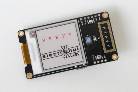
.. figure:: ../../../../../../../boards/electronut/nrf52840_papyr/doc/img/nrf52840_papyr.jpg
     :align: center
     :alt: Electronut Labs Papyr

     Electronut Labs Papyr (Credit: Electronut Labs)

More information about the board is available at https://gitlab.com/electronutlabs-public/papyr.

Hardware
********

Papyr has two external oscillators. The frequency of
the slow clock is 32.768 kHz. The frequency of the main clock
is 32 MHz.

Supported Features
==================

The nrf52840_papyr board configuration supports the following
hardware features currently:

+-----------+------------+----------------------+
| Interface | Controller | Driver/Component     |
+===========+============+======================+
| ADC       | on-chip    | adc                  |
+-----------+------------+----------------------+
| CLOCK     | on-chip    | clock_control        |
+-----------+------------+----------------------+
| FLASH     | on-chip    | flash                |
+-----------+------------+----------------------+
| GPIO      | on-chip    | gpio                 |
+-----------+------------+----------------------+
| I2C(M)    | on-chip    | i2c                  |
+-----------+------------+----------------------+
| MPU       | on-chip    | arch/arm             |
+-----------+------------+----------------------+
| NVIC      | on-chip    | arch/arm             |
+-----------+------------+----------------------+
| PWM       | on-chip    | pwm                  |
+-----------+------------+----------------------+
| RADIO     | on-chip    | Bluetooth,           |
|           |            | ieee802154           |
+-----------+------------+----------------------+
| RTC       | on-chip    | system clock         |
+-----------+------------+----------------------+
| SPI(M/S)  | on-chip    | spi                  |
+-----------+------------+----------------------+
| UART      | on-chip    | serial               |
+-----------+------------+----------------------+
| USB       | on-chip    | usb                  |
+-----------+------------+----------------------+
| WDT       | on-chip    | watchdog             |
+-----------+------------+----------------------+

Connections and IOs
===================

LED
---

* LED1 (green) = P0.13
* LED2 (blue)  = P0.15
* LED3 (red)   = P0.14

Push buttons
------------

* Reset = SW0 = P0.18 (can be used as GPIO also)

UART
----

* TX = P0.8
* RX = P0.7

I2C
---

I2C pins connected to onboard sensors (I2C_0):

* SDA = P0.5
* SCL = P0.6

SPI
---

The e-paper display is connected to the chip via SPI on the following pins (SPI_1):

* SCK  = P0.31
* MOSI = P0.29
* MISO = P1.1 (not used by the display)

NOTE: P1.1 is pin 33 in absolute enumeration.

Other pins used by the e-paper display are:

* E-ink enable = P0.11 (cuts off power to the display with MOSFET)
* CS   = P0.30
* BUSY = P0.3
* D/C  = P0.28
* RES  = P0.2

Programming and Debugging
*************************

Applications for the ``nrf52840_papyr`` board configuration can be
built and flashed in the usual way (see :ref:`build_an_application`
and :ref:`application_run` for more details); Black Magic
Probe debugger presents itself as two USB-serial ports. On Linux,
they may come up as ``/dev/ttyACM0`` and ``/dev/ttyACM1``. The first
one of these (``/dev/ttyACM0`` here) is the debugger port.
GDB can directly connect to this port without requiring a GDB server by specifying
``target external /dev/ttyACM0``. The second port acts as a
serial port, connected to the SoC.

Flashing
========

By default, papyr is configured to be used with a blackmagicprobe compatible
debugger (see _Bumpy).

Applications are flashed and run as usual (see :ref:`build_an_application` and
:ref:`application_run` for more details).

Here is an example for the :ref:`hello_world` application.

First, run your favorite terminal program to listen for output.

.. code-block:: console

   $ minicom -D <tty_device> -b 115200

Replace :code:`<tty_device>` with the serial port of Black Magic Probe.
For example, under Linux, :code:`/dev/ttyACM1`.

Then build and flash the application in the usual way.

.. zephyr-app-commands::
   :zephyr-app: samples/hello_world
   :board: nrf52840_papyr
   :goals: build flash

Debugging
=========

Debug and attach configurations are available using Black Magic Probe, and
``ninja debug``, or ``ninja attach`` (or with ``make``) are available.

NOTE: You may need to press the reset button once after using ``ninja flash``
to start executing the code. (not required with ``debug`` or ``attach``)

References
**********

.. target-notes::

.. _Electronut Labs website: https://electronut.in
.. _Store link: https://www.tindie.com/stores/ElectronutLabs/
.. _Papyr website: https://docs.electronut.in/papyr/
.. _Schematic: https://gitlab.com/electronutlabs-public/papyr/raw/master/hardware/papyr_schematic_v_0_3.pdf?inline=false
.. _Datasheet: https://gitlab.com/electronutlabs-public/papyr/raw/master/papyr_v0.3_datasheet.pdf?inline=false
.. _Nordic Semiconductor Infocenter: http://infocenter.nordicsemi.com/
.. _Black Magic Probe website: https://github.com/blacksphere/blackmagic
.. _Bumpy website: https://docs.electronut.in/bumpy/
Part 3
한국어 전문 번역
개요
Zephyr application은 nrf52840_papyr board configuration을 사용해 Electronut Labs Papyr hardware에서 실행됩니다. Nordic Semiconductor nRF52840 Arm Cortex-M4F CPU와 다음 장치를 지원합니다.
- ADC
- CLOCK
- FLASH
- GPIO
- I2C
- MPU
- NVIC
- PWM
- RADIO(Bluetooth Low Energy와 802.15.4)
- RTC
- SPI
- UART
- USB
- WDT
- COUNTER
자세한 보드 정보는 Papyr repository에서 확인할 수 있습니다.
하드웨어
Papyr에는 external oscillator 두 개가 있습니다. slow clock frequency는 32.768 kHz이고 main clock frequency는 32 MHz입니다.
지원 기능
nrf52840_papyr board configuration은 현재 다음 hardware 기능을 지원합니다.
| Interface | Controller | Driver/Component |
|---|---|---|
| ADC | on-chip | adc |
| CLOCK | on-chip | clock_control |
| FLASH | on-chip | flash |
| GPIO | on-chip | gpio |
| I2C(M) | on-chip | i2c |
| MPU | on-chip | arch/arm |
| NVIC | on-chip | arch/arm |
| PWM | on-chip | pwm |
| RADIO | on-chip | Bluetooth, ieee802154 |
| RTC | on-chip | system clock |
| SPI(M/S) | on-chip | spi |
| UART | on-chip | serial |
| USB | on-chip | usb |
| WDT | on-chip | watchdog |
연결과 I/O
LED
- LED1(green) = P0.13
- LED2(blue) = P0.15
- LED3(red) = P0.14
Push button
- Reset = SW0 = P0.18(GPIO로도 사용 가능)
UART
- TX = P0.8
- RX = P0.7
I2C
on-board sensor(I2C_0)에 연결된 I2C pin은 다음과 같습니다.
- SDA = P0.5
- SCL = P0.6
SPI
e-paper display는 SPI_1의 다음 pin으로 chip에 연결됩니다.
- SCK = P0.31
- MOSI = P0.29
- MISO = P1.1(display에서는 사용하지 않음)
P1.1은 absolute enumeration에서 pin 33입니다.
e-paper display가 사용하는 나머지 pin은 다음과 같습니다.
- E-ink enable = P0.11(MOSFET으로 display power 차단)
- CS = P0.30
- BUSY = P0.3
- D/C = P0.28
- RES = P0.2
프로그래밍과 디버깅
nrf52840_papyr board configuration용 application은 일반적인 방법으로 build하고 flash할 수 있습니다. Black Magic Probe debugger는 USB serial port 두 개로 나타납니다. Linux에서는 /dev/ttyACM0과 /dev/ttyACM1일 수 있습니다. 첫 번째 /dev/ttyACM0은 debugger port이며 GDB는 target external /dev/ttyACM0으로 별도 server 없이 직접 연결할 수 있습니다. 두 번째 port는 SoC에 연결된 serial port입니다.
Flashing
Papyr는 기본적으로 Black Magic Probe compatible debugger인 Bumpy와 함께 사용하도록 구성됩니다.
다음은 hello_world 예입니다. 먼저 terminal program으로 출력을 기다립니다.
$ minicom -D <tty_device> -b 115200<tty_device>를 Black Magic Probe serial port로 바꿉니다. Linux에서는 예를 들어 /dev/ttyACM1입니다. 그 다음 일반적인 방법으로 build하고 flash합니다.
west build -b nrf52840_papyr samples/hello_world
west flash
Debugging
Black Magic Probe를 사용하는 debug·attach configuration이 있으며 ninja debug 또는 ninja attach(또는 make)를 사용할 수 있습니다.
참고 자료
Source
출처
영어 원문에는 문단, 문서 지시문, 표, 코드, 코드 심벌, 경로를 그대로 보존했습니다.