Part 1
요약·해설
EVAL-SDP-CK1Z(SDP-K1)는 ADI component가 있는 evaluation shield를 연결하는 controller board입니다. Arduino UNO와 120-pin SDP connector, DAPLink USB-C debug interface를 제공합니다.
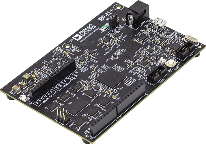
STM32F469NIH6 Cortex-M4F, 180 MHz
flash 2 MB, SRAM 384 KB, SDRAM 16 MB
Arduino UNO + 120-pin SDP + USB-C
Part 2
접을 수 있는 영어 원문 전체
영어 원문 전체 펼치기
471F08C4F193849B0DA37B428AA00436A3171D735EC5C2A45BC7FC84ED00F756
.. _adi_sdp_k1:

ADI SDP-K1
##########

Overview
********

The EVAL-SDP-CK1Z (SDP-K1) controller board is a system demonstration platform
(SDP) from Analog Devices designed to connect to evaluation shields containing
ADI components.

- STM32 microcontroller in BGA216 package
- USB 2.0 device with USB-C connector
- USB debug interface supporting CMSIS-DAP through a NXP Freescale
  microcontroller
- Flexible board power supply
    - USB VBUS 5 V max. 500 mA
    - 5.5mm DC power jack 7 - 12 V min. 300 mA
    - VIN from Arduino* compatible connectors
    - VIN from 120-pin connector 5 V min. 300 mA
- 3 color LEDs (green, orange, red) and 1 status LED
- One push-buttons: RESET
- 16MB SDRAM
- Arduino UNO and 120-pin SDP connectors

.. figure:: ../../../../../../../boards/adi/sdp_k1/doc/img/adi_sdp_k1.webp
   :align: center
   :alt: ADI SDP-K1

   ADI SDP-K1 (Credit: Analog Devices, Inc.)

More information about the board can be found on the `ADI SDP-K1 website`_.

Hardware
********

ADI SDP-K1 provides the following hardware components:

- STM32F469NIH6 in BGA216 package
- ARM |reg| 32-bit Cortex |reg| -M4 CPU with FPU
- 180 MHz max CPU frequency
- VDD of 1.8 V or 3.3 V
- 2 MB Flash
- 384 KB SRAM
- GPIO with external interrupt capability
- LCD parallel interface, 8080/6800 modes
- LCD TFT controller supporting up to XGA resolution
- MIPI |reg|  DSI host controller supporting up to 720p 30Hz resolution
- 3x12-bit ADC with 24 channels
- 2x12-bit D/A converters
- RTC
- Advanced-control Timer
- General Purpose Timers (17)
- Watchdog Timers (2)
- USART/UART (8)
- I2C (3)
- SPI (6)
- 1xSAI (serial audio interface)
- SDIO
- 2xCAN
- USB 2.0 OTG FS with on-chip PHY
- USB 2.0 OTG HS/FS with dedicated DMA, on-chip full-speed PHY and ULPI
- 10/100 Ethernet MAC with dedicated DMA
- 8- to 14-bit parallel camera
- CRC calculation unit
- True random number generator
- DMA Controller

More information about STM32F469NI can be found here:
       - `STM32F469NI product page`_
       - `STM32F469 reference manual`_

Supported Features
==================

The Zephyr stm32f469i_disco board configuration supports the following hardware features:

+-----------+------------+-------------------------------------+
| Interface | Controller | Driver/Component                    |
+===========+============+=====================================+
| UART      | on-chip    | serial port-polling;                |
|           |            | serial port-interrupt               |
+-----------+------------+-------------------------------------+
| PINMUX    | on-chip    | pinmux                              |
+-----------+------------+-------------------------------------+
| GPIO      | on-chip    | gpio                                |
+-----------+------------+-------------------------------------+

Other hardware features are not yet supported on Zephyr porting.

The default configuration can be found in
:zephyr_file:`boards/adi/sdp_k1/adi_sdp_k1_defconfig`

Pin Mapping
===========

For more details please refer to `EVAL-SDP-CK1Z User Guide`_.

Arduino UNO headers
-------------------

.. figure:: ../../../../../../../boards/adi/sdp_k1/doc/img/adi_sdp_k1_arduino.webp
   :align: center
   :alt: ADI SDP-K1 Arduino UNO headers pinout

   ADI SDP-K1 (Credit: Analog Devices, Inc.)

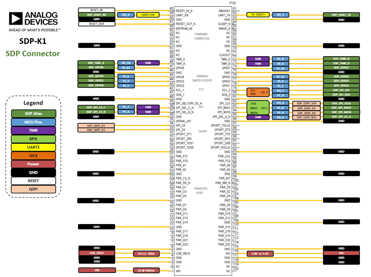
120-pin SDP connector
---------------------

.. figure:: ../../../../../../../boards/adi/sdp_k1/doc/img/adi_sdp_k1_120pin.webp
   :align: center
   :alt: ADI SDP-K1 120-pin SDP connector pinout

   ADI SDP-K1 (Credit: Analog Devices, Inc.)

Default Zephyr Peripheral Mapping:
----------------------------------

- UART_5 TX/RX : P2 (DAPLink USB-C)
- UART_5 TX/RX : P8 (DAPLink two position through hole)
- LED1 : DS6 (Red)
- LED2 : DS5 (Orange)
- LED3 : DS4 (Green)
- LED4 : DS4 (Status)

Programming and Debugging
*************************

The ADI SDP-K1 be programmed over USB using the DAPLink firmware running on an
embedded NXP Freescale microcontroller or a 10-pin ``DEBUG`` header connected
to a STLINK debugger.

DAPLink exposes a storage device, as well as USB HID and CDC Endpoints, to the
host. For more details please refer to the `Official DAPLink website`_.

Flashing
========

Flashing an application with a STLINK debugger
----------------------------------------------

First, connect the STLINK debugger to your host computer using the Micro-USB port.
Then attach the debugger to the 10-pin ``DEBUG`` header on the SDP-K1. Finally
connect the SDP-K1 to your host computer using the USB-C port.

Run a serial host program to connect with your board:

.. code-block:: console

   $ minicom -D /dev/serial/by-id/usb-ARM_DAPLink_CMSIS-DAP_<...>

Here is an example for the :ref:`hello_world` application.

.. zephyr-app-commands::
   :zephyr-app: samples/hello_world
   :board: adi_sdp_k1
   :goals: build flash

You should see the following message on the console:

.. code-block:: console

   Hello World! adi_sdp_k1

Debugging
=========

.. _ADI SDP-K1 website:
   https://www.analog.com/en/design-center/evaluation-hardware-and-software/evaluation-boards-kits/sdp-k1.html

.. _EVAL-SDP-CK1Z User Guide:
   https://www.analog.com/media/en/technical-documentation/user-guides/EVAL-SDP-CK1Z-UG-1539.pdf

.. _STM32F469NI product page:
   https://www.st.com/en/microcontrollers/stm32f469ni.html

.. _STM32F469 reference manual:
   https://www.st.com/resource/en/reference_manual/dm00127514.pdf

.. _Official DAPLink website:
   https://daplink.io/
Part 3
한국어 전문 번역
개요
EVAL-SDP-CK1Z(SDP-K1) controller board는 ADI component가 있는 evaluation shield를 연결하도록 설계한 Analog Devices System Demonstration Platform입니다.
- BGA216 STM32 MCU와 USB-C USB 2.0 device
- NXP Freescale MCU를 통해 CMSIS-DAP를 지원하는 USB debug interface
- USB VBUS 5 V 최대 500 mA, 5.5 mm DC jack 7~12 V 최소 300 mA, Arduino-compatible VIN, 120-pin connector VIN 5 V 최소 300 mA의 flexible supply
- green·orange·red LED와 status LED, RESET pushbutton
- SDRAM 16 MB, Arduino UNO와 120-pin SDP connector
하드웨어
- BGA216 STM32F469NIH6, FPU가 있는 32-bit Cortex-M4, 최대 180 MHz, VDD 1.8 V 또는 3.3 V, flash 2 MB, SRAM 384 KB
- external interrupt GPIO, 8080/6800 LCD parallel interface, XGA TFT controller, 720p 30 Hz MIPI DSI host
- 24-channel 12-bit ADC 3개, 12-bit DAC 2개, RTC
- advanced-control timer, general-purpose timer 17개, watchdog 2개
- USART/UART 8개, I2C 3개, SPI 6개, SAI 1개, SDIO, CAN 2개
- on-chip PHY USB 2.0 OTG FS, dedicated DMA와 ULPI를 갖춘 USB 2.0 OTG HS/FS
- dedicated DMA 10/100 Ethernet MAC, 8~14-bit parallel camera, CRC, TRNG, DMA controller
세부 정보는 STM32F469NI product page와 reference manual을 참고합니다.
지원 기능
adi_sdp_k1 configuration은 다음 기능을 지원하며 나머지 hardware는 아직 Zephyr port에서 지원하지 않습니다. 기본 설정은 boards/adi/sdp_k1/adi_sdp_k1_defconfig에 있습니다.
| Interface | Controller | Driver/Component |
|---|---|---|
| UART | on-chip | serial polling·interrupt |
| PINMUX | on-chip | pinmux |
| GPIO | on-chip | gpio |
Pin mapping
자세한 내용은 EVAL-SDP-CK1Z User Guide를 참고합니다.
Arduino UNO header
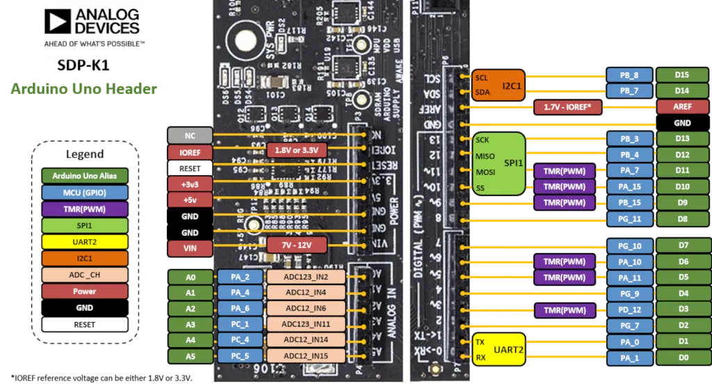
120-pin SDP connector
Zephyr 기본 peripheral mapping
UART_5 TX/RX: P2, DAPLink USB-CUART_5 TX/RX: P8, DAPLink 2-position through-holeLED1: DS6 redLED2: DS5 orangeLED3: DS4 greenLED4: DS4 status
프로그래밍과 디버깅
embedded NXP Freescale MCU의 DAPLink firmware를 USB로 사용하거나, STLINK debugger를 10-pin DEBUG header에 연결해 program할 수 있습니다. DAPLink는 storage device, USB HID와 CDC endpoint를 host에 제공합니다.
STLINK로 application flash
STLINK debugger를 Micro-USB로 host에 연결하고 SDP-K1의 10-pin DEBUG header에 연결합니다. SDP-K1도 USB-C로 host에 연결한 뒤 serial console을 엽니다.
$ minicom -D /dev/serial/by-id/usb-ARM_DAPLink_CMSIS-DAP_<...>
$ west build -b adi_sdp_k1 samples/hello_world
$ west flash
console에는 다음 message가 표시돼야 합니다.
Hello World! adi_sdp_k1참고 자료
Source
출처
영어 원문에는 문단, 문서 지시문, 표, 코드, 코드 심벌, 경로를 그대로 보존했습니다.