Part 1
요약·해설
ItsyBitsy nRF52840 Express는 36 × 18 mm 크기에 GPIO 21개, USB, QSPI flash 2 MB와 RGB DotStar를 배치한 소형 wireless board입니다. Bluetooth LE와 IEEE 802.15.4도 지원합니다.
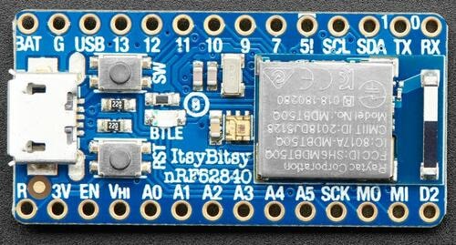
Bluetooth LE와 IEEE 802.15.4
internal flash 1 MB + QSPI flash 2 MB
ITSY840BOOT drive에 zephyr.uf2 복사
Part 2
접을 수 있는 영어 원문 전체
영어 원문 전체 펼치기
D9B7D202DD40EC76E051F7CE33F137A306A651E8F0EC02436E40F280A5777FEA
.. _adafruit_itsybitsy_nrf52840:

Adafruit ItsyBitsy nRF52840
###########################

Overview
********

The Adafruit ItsyBitsy nRF52840 Express is a small (36 mm x 18 mm) ARM
development board with an onboard RGB LED, USB port, 2 MB of QSPI flash,
and range of I/O broken out onto 21 GPIO pins.

This development kit has the following features:

* :abbr:`ADC (Analog to Digital Converter)`
* CLOCK
* FLASH
* :abbr:`GPIO (General Purpose Input Output)`
* :abbr:`I2C (Inter-Integrated Circuit)`
* :abbr:`I2S (Inter-Integrated Sound)`
* :abbr:`MPU (Memory Protection Unit)`
* :abbr:`NVIC (Nested Vectored Interrupt Controller)`
* :abbr:`PWM (Pulse Width Modulation)`
* :abbr:`QSPI (Quad Serial Peripheral Interface)`
* RADIO (Bluetooth Low Energy and 802.15.4)
* :abbr:`RTC (nRF RTC System Clock)`
* :abbr:`SPI (Serial Peripheral Interface)`
* :abbr:`UARTE (Universal asynchronous receiver-transmitter)`
* :abbr:`USB (Universal Serial Bus)`
* :abbr:`WDT (Watchdog Timer)`

.. image:: ../../../../../../../boards/adafruit/itsybitsy/doc/img/adafruit_itsybitsy_nrf52840.jpeg
     :align: center
     :alt: Adafruit ItsyBitsy nRF52840 Express

Hardware
********
- nRF52840 ARM Cortex-M4F CPU at 64MHz
- 1 MB of flash memory and 256 KB of SRAM
- 2 MB of QSPI flash
- A user LED
- A user switch
- An RGB DotStar LED
- Native USB port
- One reset button

Supported Features
==================

The Adafruit ItsyBitsy nRF52840 board configuration supports the
following hardware features:

+-----------+------------+----------------------+
| Interface | Controller | Driver/Component     |
+===========+============+======================+
| ADC       | on-chip    | adc                  |
+-----------+------------+----------------------+
| CLOCK     | on-chip    | clock_control        |
+-----------+------------+----------------------+
| FLASH     | on-chip    | flash                |
+-----------+------------+----------------------+
| GPIO      | on-chip    | gpio                 |
+-----------+------------+----------------------+
| I2C       | on-chip    | i2c                  |
+-----------+------------+----------------------+
| MPU       | on-chip    | arch/arm             |
+-----------+------------+----------------------+
| NVIC      | on-chip    | arch/arm             |
+-----------+------------+----------------------+
| PWM       | on-chip    | pwm                  |
+-----------+------------+----------------------+
| QSPI(M)   | on-chip    | nor                  |
+-----------+------------+----------------------+
| RADIO     | on-chip    | Bluetooth,           |
|           |            | ieee802154           |
+-----------+------------+----------------------+
| RTC       | on-chip    | system clock         |
+-----------+------------+----------------------+
| SPI       | on-chip    | spi                  |
+-----------+------------+----------------------+
| UARTE     | on-chip    | serial               |
+-----------+------------+----------------------+
| USB       | on-chip    | usb                  |
+-----------+------------+----------------------+
| WDT       | on-chip    | watchdog             |
+-----------+------------+----------------------+

Other hardware features have not been enabled yet for this board.

Connections and IOs
===================

The `Adafruit ItsyBitsy nRF52840 Express Learn site`_ has detailed
information about the board including `pinouts`_ and the `schematic`_.

LED
---

* LED0 (red) = P0.06

* LED1 (Adafruit DotStar)

    * DATA = P0.08

    * CLK = P1.09

Push buttons
------------

* SWITCH = P0.29

* RESET = P0.18

Logging
-------

Logging is done using the USB-CDC port. See the :zephyr:code-sample:`logging` sample
or the :zephyr:code-sample:`usb-cdc-acm-console` sample applications to see how this works.

Testing LEDs and buttons on the Adafruit ItsyBitsy nRF52840 Express
*******************************************************************
The :zephyr:code-sample:`button` sample lets you test the buttons (switches) and the red LED.
The :zephyr:code-sample:`blinky` sample lets you test the red LED.

The DotStar LED has been implemented as a SPI device and can be tested
with the :zephyr:code-sample:`led-strip` sample application.

You can build and flash the examples to make sure Zephyr is running correctly on
your board. The button and LED definitions can be found in
:zephyr_file:`boards/adafruit/itsybitsy/adafruit_itsybitsy_nrf52840.dts`.

Programming and Debugging
*************************
The ItsyBitsy ships with the BOSSA compatible UF2 bootloader.  The
bootloader can be entered by quickly tapping the reset button twice.

First time setup
================
Some versions of this board were shipped with a buggy bootloader.
Ensure that the bootloader is up to date by following the
`Adafruit UF2 Bootloader update`_ tutorial. Note that this tutorial
was made for the Adafruit Feather nRF52840, but the steps to update
the bootloader are the same for the ItsyBitsy. The files for the
ItsyBitsy bootloader can be found in the `Adafruit nRF52 Bootloader repo`_.

The building and flashing of Zephyr applications have been tested with
release 0.7.0 of the UF2 bootloader.

Flashing
========
Flashing is done by dragging and dropping the built Zephyr UF2-file
into the :code:`ITSY840BOOT` drive.

#. Build the Zephyr kernel and the :zephyr:code-sample:`blinky`
   sample application:

   .. zephyr-app-commands::
      :zephyr-app: samples/basic/blinky
      :board: adafruit_itsybitsy/nrf52840
      :goals: build
      :compact:

#. Connect the ItsyBitsy to your host computer using USB

#. Tap the reset button twice quickly to enter bootloader mode

#. Flash the image:

   Drag and drop the file :code:`samples/basic/blinky/build/zephyr/zephyr.uf2`
   into :code:`ITSY840BOOT`

The device will disconnect and you should see the red LED blink.

References
**********

.. target-notes::

.. _Adafruit ItsyBitsy nRF52840 Express Learn site:
    https://learn.adafruit.com/adafruit-itsybitsy-nrf52840-express

.. _pinouts:
    https://learn.adafruit.com/adafruit-itsybitsy-nrf52840-express/pinouts

.. _schematic:
    https://learn.adafruit.com/adafruit-itsybitsy-nrf52840-express/downloads

.. _Adafruit UF2 Bootloader update:
    https://learn.adafruit.com/introducing-the-adafruit-nrf52840-feather/update-bootloader

.. _Adafruit nRF52 Bootloader repo:
    https://github.com/adafruit/Adafruit_nRF52_Bootloader/releases
Part 3
한국어 전문 번역
개요
Adafruit ItsyBitsy nRF52840 Express는 36 mm × 18 mm 크기의 소형 Arm development board입니다. on-board RGB LED, USB port, QSPI flash 2 MB와 GPIO pin 21개로 외부에 연결된 여러 I/O를 제공합니다.
ADC, CLOCK, FLASH, GPIO, I2C, I2S, MPU, NVIC, PWM, QSPI, Bluetooth LE·802.15.4 RADIO, RTC, SPI, UARTE, USB와 WDT 기능을 갖습니다.
하드웨어
- 64 MHz nRF52840 Arm Cortex-M4F CPU
- flash memory 1 MB, SRAM 256 KB
- QSPI flash 2 MB
- user LED
- user switch
- RGB DotStar LED
- native USB port
- reset button 1개
지원 기능
Adafruit ItsyBitsy nRF52840 board configuration은 다음 hardware 기능을 지원합니다.
| Interface | Controller | Driver/Component |
|---|---|---|
| ADC | on-chip | adc |
| CLOCK | on-chip | clock_control |
| FLASH | on-chip | flash |
| GPIO | on-chip | gpio |
| I2C | on-chip | i2c |
| MPU | on-chip | arch/arm |
| NVIC | on-chip | arch/arm |
| PWM | on-chip | pwm |
| QSPI(M) | on-chip | nor |
| RADIO | on-chip | Bluetooth, ieee802154 |
| RTC | on-chip | system clock |
| SPI | on-chip | spi |
| UARTE | on-chip | serial |
| USB | on-chip | usb |
| WDT | on-chip | watchdog |
그 밖의 hardware 기능은 아직 활성화되지 않았습니다.
연결과 I/O
Adafruit ItsyBitsy nRF52840 Express Learn site에서 pinout과 schematic을 확인할 수 있습니다.
LED
LED0(red) =P0.06LED1(Adafruit DotStar): DATA =P0.08, CLK =P1.09
Push button
SWITCH = P0.29RESET = P0.18
Logging
logging은 USB-CDC port를 사용합니다. logging sample 또는 usb-cdc-acm-console sample에서 동작 방식을 확인할 수 있습니다.
LED와 button 시험
button sample은 switch와 red LED를, blinky sample은 red LED를 시험합니다. DotStar LED는 SPI device로 구현되며 led-strip sample로 시험할 수 있습니다. board 정의는 boards/adafruit/itsybitsy/adafruit_itsybitsy_nrf52840.dts에 있습니다.
프로그래밍과 디버깅
ItsyBitsy에는 BOSSA-compatible UF2 bootloader가 설치돼 있으며 reset을 빠르게 두 번 누르면 진입합니다.
최초 설정
일부 version은 문제가 있는 bootloader로 출하됐습니다. Adafruit UF2 Bootloader update tutorial에 따라 갱신합니다. tutorial은 Feather nRF52840용이지만 ItsyBitsy도 절차가 같고, ItsyBitsy file은 Adafruit nRF52 Bootloader repository에 있습니다. Zephyr application build와 flashing은 UF2 bootloader release 0.7.0에서 시험됐습니다.
Flashing
build한 Zephyr UF2 file을 ITSY840BOOT drive로 drag-and-drop합니다.
blinky를 build합니다.west build -b adafruit_itsybitsy/nrf52840 samples/basic/blinky- USB로 ItsyBitsy를 host에 연결합니다.
- reset을 빠르게 두 번 눌러 bootloader mode로 진입합니다.
samples/basic/blinky/build/zephyr/zephyr.uf2를ITSY840BOOTdrive로 끌어다 놓습니다.
device 연결이 끊겼다가 다시 시작되고 red LED가 깜박여야 합니다.
참고 자료
Source
출처
영어 원문에는 문단, 문서 지시문, 표, 코드, 코드 심벌, 경로를 그대로 보존했습니다.