Part 1
요약·해설
Neonkey는 Argonkey와 비슷한 sensor hub 역할을 하지만 STM32F411CE, 512 KB flash, 128 KB SRAM을 사용하며 내장 sensor 구성이 다릅니다. 기본 console은 USART1 115200 8N1이고, ROM bootloader와 SWD 두 경로를 지원합니다.
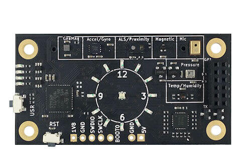
84 MHz STM32F411CE Cortex-M4F, flash 512 KB, SRAM 128 KB
온습도, 압력, 조도/근접, 지자기, IMU, Hall, microphone
BOOT0/USR/RST pattern의 ROM loader 또는 P4 SWD
Part 2
접을 수 있는 영어 원문 전체
영어 원문 전체 펼치기
EB773182BFAAA42982B47F2E349AE12EF8D9A2B3A301F05CB565E9C8986E0626
.. _96b_neonkey:

96Boards Neonkey
################

Overview
********

96Boards Neonkey board is based on the STMicroelectronics STM32F411CE
Cortex M4 CPU.

.. figure:: ../../../../../../../boards/96boards/neonkey/doc/img/96b_neonkey.jpg
     :align: center
     :alt: 96Boards Neonkey

     96Boards Neonkey

This board acts as a sensor hub platform for all 96Boards compliant
family products. It can also be used as a standalone board.

Hardware
********

96Boards Neonkey provides the following hardware components:

- STM32F411CE in UFQFPN48 package
- ARM |reg| 32-bit Cortex |reg|-M4 CPU with FPU
- 84 MHz max CPU frequency
- 1.8V work voltage
- 512 KB Flash
- 128 KB SRAM
- On board sensors:

  - Temperature/Humidity: SI7034-A10
  - Pressure: BMP280
  - ALS/Proximity: RPR-0521RS
  - Geomagnetic: BMM150
  - Accelerometer/Gyroscope: BMI160
  - AMR Hall sensor: MRMS501A
  - Microphone: SPK0415HM4H-B

- 4 User LEDs
- 15 General purpose LEDs
- GPIO with external interrupt capability
- I2C (3)
- SPI (1)
- I2S (1)

Supported Features
==================

The Zephyr 96b_neonkey board configuration supports the following hardware
features:

+-----------+------------+-------------------------------------+
| Interface | Controller | Driver/Component                    |
+===========+============+=====================================+
| NVIC      | on-chip    | nested vector interrupt controller  |
+-----------+------------+-------------------------------------+
| SYSTICK   | on-chip    | system clock                        |
+-----------+------------+-------------------------------------+
| UART      | on-chip    | serial port                         |
+-----------+------------+-------------------------------------+
| GPIO      | on-chip    | gpio                                |
+-----------+------------+-------------------------------------+
| PINMUX    | on-chip    | pinmux                              |
+-----------+------------+-------------------------------------+
| FLASH     | on-chip    | flash                               |
+-----------+------------+-------------------------------------+
| SPI       | on-chip    | spi                                 |
+-----------+------------+-------------------------------------+
| I2C       | on-chip    | i2c                                 |
+-----------+------------+-------------------------------------+

More details about the board can be found at `96Boards website`_.

The default board configuration can be found in
:zephyr_file:`boards/96boards/neonkey/96b_neonkey_defconfig`

Connections and IOs
===================

LED
---

- LED1 / User1 LED = PB12
- LED2 / User2 LED = PB13
- LED3 / User3 LED = PB14
- LED4 / User4 LED = PB15

Push buttons
------------

- BUTTON = RST (SW1)
- BUTTON = USR (SW2)

System Clock
============

96Boards Neonkey can be driven by an internal oscillator as well as the main
PLL clock. By default System clock is sourced by PLL clock at 84MHz, driven
by internal oscillator.

Serial Port
===========

On 96Boards Neonkey Zephyr console output is assigned to USART1.
Default settings are 115200 8N1.

I2C
---

96Boards Neonkey board has up to 3 I2Cs. The default I2C mapping for Zephyr is:

- I2C1_SCL : PB6
- I2C1_SDA : PB7
- I2C2_SCL : PB10
- I2C2_SDA : PB3
- I2C3_SCL : PA8
- I2C3_SCL : PB4

SPI
---

96Boards Neonkey board has one SPI. The default SPI mapping for Zephyr is:

- SPI1_NSS  : PA4
- SPI1_SCK  : PA5
- SPI1_MISO : PA6
- SPI1_MOSI : PA7

Programming and Debugging
*************************

Building
========

Here is an example for building the :ref:`hello_world` application.

.. zephyr-app-commands::
   :zephyr-app: samples/hello_world
   :board: 96b_neonkey
   :goals: build

Flashing
========

96Boards Neonkey can be flashed by two methods, one using the ROM
bootloader and another using the SWD debug port (which requires additional
hardware).

Using ROM bootloader:
---------------------

ROM bootloader can be triggered by the following pattern:

1. Connect BOOT0 to VDD (link JTAG pins 1 and 5 on P4 header)
2. Press and hold the USR button
3. Press and release the RST button

More detailed information on activating the ROM bootloader can be found in
Chapter 29 of Application note `AN2606`_. The ROM bootloader supports flashing
via UART, I2C and SPI protocols.

For flashing, `stm32flash`_ command line utility can be used. The following
command will flash the ``zephyr.bin`` binary to the Neonkey board using UART
and starts its execution:

.. code-block:: console

   $ stm32flash -w zephyr.bin -v -g 0x08000000 /dev/ttyS0

.. note::
   The above command assumes that Neonkey board is connected to
   serial port ``/dev/ttyS0``.

Using SWD debugger:
-------------------

For flashing via SWD debug port, 0.1" male header must be soldered at P4
header available at the bottom of the board, near RST button.

Use the `Black Magic Debug Probe`_ as an SWD programmer, which can
be connected to the P4 header using its flying leads and its 20 Pin
JTAG Adapter Board Kit. When plugged into your host PC, the Black
Magic Debug Probe enumerates as a USB serial device as documented on
its `Getting started page`_.

It also uses the GDB binary provided with the Zephyr SDK,
``arm-zephyr-eabi-gdb``. Other GDB binaries, such as the GDB from GCC
ARM Embedded, can be used as well.

.. code-block:: console

   $ arm-zephyr-eabi-gdb -q zephyr.elf
   (gdb) target extended-remote /dev/ttyACM0
   Remote debugging using /dev/ttyACM0
   (gdb) monitor swdp_scan
   Target voltage: 1.8V
   Available Targets:
   No. Att Driver
    1      STM32F4xx
   (gdb) attach 1
   Attaching to Remote target
   0x080005d0 in ?? ()
   (gdb) load

Debugging
=========

After flashing 96Boards Neonkey, it can be debugged using the same
GDB instance. To reattach, just follow the same steps above, till
"attach 1". You can then debug as usual with GDB. In particular, type
"run" at the GDB prompt to restart the program you've flashed.

References
**********

.. _96Boards website:
   https://www.96boards.org/product/neonkey/

.. _AN2606:
   https://www.st.com/resource/en/application_note/cd00167594.pdf

.. _stm32flash:
   https://sourceforge.net/p/stm32flash/wiki/Home/

.. _Black Magic Debug Probe:
   https://github.com/blacksphere/blackmagic/wiki

.. _Getting started page:
   https://github.com/blacksphere/blackmagic/wiki/Getting-Started
Part 3
한국어 전문 번역
개요
96Boards Neonkey 보드는 STMicroelectronics STM32F411CE Cortex-M4 CPU를 기반으로 합니다.
이 보드는 96Boards 규격 제품군을 위한 sensor hub platform으로 동작하며, 독립형 보드로도 사용할 수 있습니다.
하드웨어
- UFQFPN48 package의 STM32F411CE
- FPU를 갖춘 Arm 32-bit Cortex-M4 CPU, 최대 84 MHz
- 동작 전압 1.8 V, flash 512 KB, SRAM 128 KB
- 내장 sensor
- 온도/습도: SI7034-A10
- 압력: BMP280
- 주변광/근접: RPR-0521RS
- 지자기: BMM150
- 가속도계/gyroscope: BMI160
- AMR Hall sensor: MRMS501A
- microphone: SPK0415HM4H-B
- user LED 4개, general-purpose LED 15개
- 외부 interrupt 기능을 갖춘 GPIO
- I2C 3개, SPI 1개, I2S 1개
지원 기능
Zephyr의 96b_neonkey 보드 설정은 다음 기능을 지원합니다.
| Interface | Controller | Driver/Component |
|---|---|---|
| NVIC | on-chip | nested vector interrupt controller |
| SYSTICK | on-chip | system clock |
| UART | on-chip | serial port |
| GPIO | on-chip | gpio |
| PINMUX | on-chip | pinmux |
| FLASH | on-chip | flash |
| SPI | on-chip | spi |
| I2C | on-chip | i2c |
자세한 보드 정보는 96Boards website에서 확인할 수 있습니다. 기본 설정 파일은 boards/96boards/neonkey/96b_neonkey_defconfig입니다.
연결과 I/O
LED
LED1 / User1 LED = PB12LED2 / User2 LED = PB13LED3 / User3 LED = PB14LED4 / User4 LED = PB15
Push button
BUTTON = RST (SW1)BUTTON = USR (SW2)
System clock
Neonkey는 internal oscillator 또는 main PLL clock으로 구동할 수 있습니다. 기본적으로 internal oscillator가 구동하는 PLL clock에서 84 MHz system clock을 얻습니다.
Serial port
Zephyr console output은 USART1에 할당되며 기본 설정은 115200 8N1입니다.
I2C
Neonkey에는 최대 3개의 I2C가 있습니다. Zephyr 기본 mapping은 다음과 같습니다.
I2C1_SCL: PB6I2C1_SDA: PB7I2C2_SCL: PB10I2C2_SDA: PB3I2C3_SCL: PA8I2C3_SCL: PB4
SPI
Neonkey에는 SPI가 하나 있습니다.
SPI1_NSS: PA4SPI1_SCK: PA5SPI1_MISO: PA6SPI1_MOSI: PA7
프로그래밍과 디버깅
빌드
hello_world 애플리케이션 빌드 예는 다음과 같습니다.
# Zephyr 저장소 루트에서
west build -b 96b_neonkey samples/hello_world
Flashing
Neonkey는 ROM bootloader 또는 별도 하드웨어가 필요한 SWD debug port로 flash할 수 있습니다.
ROM bootloader 사용
다음 pattern으로 ROM bootloader를 실행합니다.
- BOOT0를 VDD에 연결: P4 header의 JTAG pin 1과 5 연결
- USR button을 누른 상태로 유지
- RST button을 눌렀다 놓기
자세한 활성화 방법은 AN2606 Chapter 29에 있습니다. ROM bootloader는 UART, I2C, SPI protocol flashing을 지원합니다. stm32flash로 UART를 통해 zephyr.bin을 기록하고 실행하는 명령은 다음과 같습니다.
$ stm32flash -w zephyr.bin -v -g 0x08000000 /dev/ttyS0SWD debugger 사용
SWD로 flash하려면 보드 아래쪽 RST button 근처의 P4 header에 0.1 inch male header를 납땜해야 합니다. Black Magic Debug Probe를 flying lead와 20 Pin JTAG Adapter Board Kit로 P4에 연결합니다. PC에 연결하면 USB serial device로 인식됩니다.
Zephyr SDK의 arm-zephyr-eabi-gdb를 사용하며 다른 Arm GDB도 사용할 수 있습니다.
$ arm-zephyr-eabi-gdb -q zephyr.elf
(gdb) target extended-remote /dev/ttyACM0
Remote debugging using /dev/ttyACM0
(gdb) monitor swdp_scan
Target voltage: 1.8V
Available Targets:
No. Att Driver
 1      STM32F4xx
(gdb) attach 1
Attaching to Remote target
0x080005d0 in ?? ()
(gdb) load
Debugging
flash 후 같은 GDB instance로 debug할 수 있습니다. 다시 연결할 때는 위 절차를 attach 1까지 반복합니다. 이후 일반적인 GDB 명령을 사용하며, run을 입력하면 flash한 program을 다시 시작합니다.
참고 자료
- 96Boards Neonkey website
- AN2606
- stm32flash
- Black Magic Debug Probe
- Getting started page
Source
출처
영어 원문에는 문단, 문서 지시문, 표, 코드, 코드 심벌, 경로를 그대로 보존했습니다.