Part 1
요약·해설
Centralized·distributed controller, GPIO 경계, standard·custom·dynamic state, 두 Devicetree 표현, driver API 계약을 설명합니다.
centralized · distributed
default · sleep · custom
Devicetree · driver API
Part 2
접을 수 있는 영어 원문 전체
영어 원문 전체 펼치기
F01B3A8DA41CD364D0CE7DAA67C169275B900798BD74C165E35870A3A633CFF6
.. _pinctrl-guide:

Pin Control
###########

This is a high-level guide to pin control. See :ref:`pinctrl_api` for API
reference material.

Introduction
************

The hardware blocks that control pin multiplexing and pin configuration
parameters such as pin direction, pull-up/down resistors, etc. are named **pin
controllers**. The pin controller's main users are SoC hardware peripherals,
since the controller enables exposing peripheral signals, like for example,
map ``I2C0`` ``SDA`` signal to pin ``PX0``. Not only that, but it usually allows
configuring certain pin settings that are necessary for the correct functioning
of a peripheral, for example, the slew-rate depending on the operating
frequency. The available configuration options are vendor/SoC dependent and can
range from simple pull-up/down options to more advanced settings such as
debouncing, low-power modes, etc.

The way pin control is implemented in hardware is vendor/SoC specific. It is
common to find a *centralized* approach, that is, all pin configuration
parameters are controlled by a single hardware block (typically named pinmux),
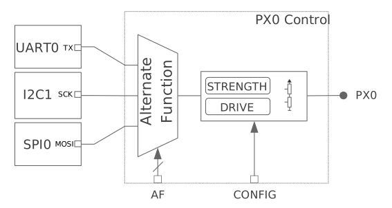
including signal mapping. The figure below illustrates this
approach. ``PX0`` can be mapped to ``UART0_TX``, ``I2C0_SCK`` or ``SPI0_MOSI``
depending on the ``AF`` control bits. Other configuration parameters such as
pull-up/down are controlled in the same block via ``CONFIG`` bits. This model is
used by several SoC families, such as many from NXP and STM32.

.. figure:: ../../../../hardware/pinctrl/images/hw-cent-control.svg

    Example of pin control centralized into a single per-pin block

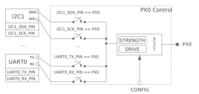
Other vendors/SoCs use a *distributed* approach. In such case, the pin mapping
and configuration are controlled by multiple hardware blocks.
The figure below illustrates a distributed approach where pin
mapping is controlled by peripherals, such as in Nordic nRF SoCs.

.. figure:: ../../../../hardware/pinctrl/images/hw-dist-control.svg

    Example pin control distributed between peripheral registers and per-pin block

From a user perspective, there is no difference in pin controller usage
regardless of the hardware implementation: a user will always apply a state.
The only difference lies in the driver implementation. In general, implementing
a pin controller driver for a hardware that uses a distributed approach requires
more effort, since the driver needs to gather knowledge of peripheral dependent
registers.

Pin control vs. GPIO
====================

Some functionality covered by a pin controller driver overlaps with GPIO
drivers. For example, pull-up/down resistors can usually be enabled by both the
pin control driver and the GPIO driver. In Zephyr context, the pin control
driver purpose is to perform peripheral signal multiplexing and configuration of
other pin parameters required for the correct operation of that peripheral.
Therefore, the main users of the pin control driver are SoC peripherals. In
contrast, GPIO drivers are for general purpose control of a pin, that is, when
its logic level is read or controlled manually.

State model
***********

For a device driver to operate correctly, a certain pin configuration needs to
be applied. Some device drivers require a static configuration, usually set up
at initialization time. Others need to change the configuration at runtime
depending on the operating conditions, for example, to enable a low-power mode
when suspending the device. Such requirements are modeled using **states**, a
concept that has been adapted from the one in the Linux kernel. Each device
driver owns a set of states. Each state has a unique name and contains a full
pin configuration set (see the figure below). This effectively
means that states are independent of each other, so they do not need to be
applied in any specific order. Another advantage of the state model is that it
isolates device drivers from pin configuration.

.. table:: Example pin configuration encoded using the states model
    :align: center

    +----+------------------+----+------------------+
    | ``UART0`` peripheral                          |
    +====+==================+====+==================+
    | ``default`` state     | ``sleep`` state       |
    +----+------------------+----+------------------+
    | TX | - Pin: PA0       | TX | - Pin: PA0       |
    |    | - Pull: NONE     |    | - Pull: NONE     |
    |    | - Low Power: NO  |    | - Low Power: YES |
    +----+------------------+----+------------------+
    | RX | - Pin: PA1       | RX | - Pin: PA1       |
    |    | - Pull: UP       |    | - Pull: NONE     |
    |    | - Low Power: NO  |    | - Low Power: YES |
    +----+------------------+----+------------------+

Standard states
===============

The name assigned to pin control states or the number of them is up to the
device driver requirements. In many cases a single state applied at
initialization time will be sufficient, but in some other cases more will be
required. In order to make things consistent, a naming convention has been
established for the most common use cases. The figure below
details the standardized states and its purpose.

.. table:: Standardized state names
    :align: center

    +-------------+----------------------------------+-------------------------+
    | State       | Identifier                       | Purpose                 |
    +-------------+----------------------------------+-------------------------+
    | ``default`` | :c:macro:`PINCTRL_STATE_DEFAULT` | State of the pins when  |
    |             |                                  | the device is in        |
    |             |                                  | operational state       |
    +-------------+----------------------------------+-------------------------+
    | ``sleep``   | :c:macro:`PINCTRL_STATE_SLEEP`   | State of the pins when  |
    |             |                                  | the device is in low    |
    |             |                                  | power or sleep modes    |
    +-------------+----------------------------------+-------------------------+

Note that other standard states could be introduced in the future.

Custom states
=============

Some device drivers may require using custom states beyond the standard ones. To
achieve that, the device driver needs to have in its scope definitions for the
custom state identifiers named as ``PINCTRL_STATE_{STATE_NAME}``, where
``{STATE_NAME}`` is the capitalized state name. For example, if ``mystate`` has
to be supported, a definition named ``PINCTRL_STATE_MYSTATE`` needs to be
in the driver's scope.

.. note::
    It is important that custom state identifiers start from
    :c:macro:`PINCTRL_STATE_PRIV_START`

If custom states need to be accessed from outside the driver, for example to
perform dynamic pin control, custom identifiers should be placed in a header
that is publicly accessible.

Skipping states
===============

In most situations, the states defined in Devicetree will be the ones used in
the compiled firmware. However, there are some cases where certain states will
be conditionally used depending on a compilation flag. A typical case is the
``sleep`` state. This state is only used in practice if
:kconfig:option:`CONFIG_PM` or :kconfig:option:`CONFIG_PM_DEVICE` is enabled.
If a firmware variant without these power management configurations is needed,
one should in theory remove the ``sleep`` state from Devicetree to not waste ROM
space storing such unused state.

States can be skipped by the ``pinctrl`` Devicetree macros if a definition named
``PINCTRL_SKIP_{STATE_NAME}`` expanding to ``1`` is present when pin control
configuration is defined. In case of the ``sleep`` state, the ``pinctrl`` API
already provides such definition conditional to the availability of device power
management:

.. code-block:: c

    #if !defined(CONFIG_PM) && !defined(CONFIG_PM_DEVICE)
    /** Out of power management configurations, ignore "sleep" state. */
    #define PINCTRL_SKIP_SLEEP 1
    #endif

Dynamic pin control
*******************

Dynamic pin control refers to the capability of changing pin configuration
at runtime. This feature can be useful in situations where the same firmware
needs to run onto slightly different boards, each having a peripheral routed at
a different set of pins. This feature can be enabled by setting
:kconfig:option:`CONFIG_PINCTRL_DYNAMIC`.

.. note::

    Dynamic pin control should only be used on devices that have not been
    initialized. Changing pin configurations while a device is operating may
    lead to unexpected behavior. Since Zephyr does not support device
    de-initialization yet, this functionality should only be used during early
    boot stages.

One of the effects of enabling dynamic pin control is that
:c:struct:`pinctrl_dev_config` will be stored in RAM instead of ROM (not states
or pin configurations, though). The user can then use
:c:func:`pinctrl_update_states` to update the states stored in
:c:struct:`pinctrl_dev_config` with a new set. This effectively means that the
device driver will apply the pin configurations stored in the updated states
when it applies a state.

Devicetree representation
*************************

Because Devicetree is meant to describe hardware, it is the natural choice when
it comes to storing pin control configuration. In the following sections you
will find an overview on how states and pin configurations are represented in
Devicetree.

States
======

Given a device, each of its pin control state is represented in Devicetree by
``pinctrl-N`` properties, being ``N`` the state index starting from zero. The
``pinctrl-names`` property is then used to assign a unique identifier for each
state property by index, for example, ``pinctrl-names`` list entry 0 is the name
for ``pinctrl-0``.

.. code-block:: devicetree

    periph0: periph@0 {
        ...
        /* state 0 ("default") */
        pinctrl-0 = <...>;
        ...
        /* state N ("mystate") */
        pinctrl-N = <...>;
        /* names for state 0 up to state N */
        pinctrl-names = "default", ..., "mystate";
        ...
    };

Pin configuration
=================

There are multiple ways to represent the pin configurations in Devicetree.
However, all end up encoding the same information: the pin multiplexing and the
pin configuration parameters. For example, ``UART_RX`` is mapped to ``PX0`` and
pull-up is enabled. The representation choice largely depends on each
vendor/SoC, so the Devicetree binding files for the pin control drivers are the
best place to look for details.

A popular and versatile option is shown in the example below. One of the
advantages of this choice is the grouping capability based on shared pin
configuration. This allows to reduce the verbosity of the pin control
definitions. Another advantage is that the pin configuration parameters for a
particular state are enclosed in a single Devicetree node.

.. code-block:: devicetree

    /* board.dts */
    #include "board-pinctrl.dtsi"

    &periph0 {
        pinctrl-0 = <&periph0_default>;
        pinctrl-names = "default";
    };

.. code-block:: c

    /* vnd-soc-pkgxx.h
     * File with valid mappings for a specific package (may be autogenerated).
     * This file is optional, but recommended.
     */
    ...
    #define PERIPH0_SIGA_PX0 VNDSOC_PIN(X, 0, MUX0)
    #define PERIPH0_SIGB_PY7 VNDSOC_PIN(Y, 7, MUX4)
    #define PERIPH0_SIGC_PZ1 VNDSOC_PIN(Z, 1, MUX2)
    ...

.. code-block:: devicetree

    /* board-pinctrl.dtsi */
    #include <vnd-soc-pkgxx.h>

    &pinctrl {
        /* Node with pin configuration for default state */
        periph0_default: periph0_default {
            group1 {
                /* Mappings: PERIPH0_SIGA -> PX0, PERIPH0_SIGC -> PZ1 */
                pinmux = <PERIPH0_SIGA_PX0>, <PERIPH0_SIGC_PZ1>;
                /* Pins PX0 and PZ1 have pull-up enabled */
                bias-pull-up;
            };
            ...
            groupN {
                /* Mappings: PERIPH0_SIGB -> PY7 */
                pinmux = <PERIPH0_SIGB_PY7>;
            };
        };
    };

Another popular model is based on having a node for each pin configuration and
state. While this model may lead to shorter board pin control files, it also
requires to have one node for each pin mapping and state, since in general,
nodes can not be re-used for multiple states. This method is discouraged if
autogeneration is not an option.

.. note::

   Because all Devicetree information is parsed into a C header, it is important
   to make sure its size is kept to a minimum. For this reason it is important
   to prefix pre-generated nodes with ``/omit-if-no-ref/``. This prefix makes
   sure that the node is discarded when not used.

.. code-block:: devicetree

    /* board.dts */
    #include "board-pinctrl.dtsi"

    &periph0 {
        pinctrl-0 = <&periph0_siga_px0_default &periph0_sigb_py7_default
                     &periph0_sigc_pz1_default>;
        pinctrl-names = "default";
    };

.. code-block:: devicetree

    /* vnd-soc-pkgxx.dtsi
     * File with valid nodes for a specific package (may be autogenerated).
     * This file is optional, but recommended.
     */

    &pinctrl {
        /* Mapping for PERIPH0_SIGA -> PX0, to be used for default state */
        /omit-if-no-ref/ periph0_siga_px0_default: periph0_siga_px0_default {
            pinmux = <VNDSOC_PIN(X, 0, MUX0)>;
        };

        /* Mapping for PERIPH0_SIGB -> PY7, to be used for default state */
        /omit-if-no-ref/ periph0_sigb_py7_default: periph0_sigb_py7_default {
            pinmux = <VNDSOC_PIN(Y, 7, MUX4)>;
        };

        /* Mapping for PERIPH0_SIGC -> PZ1, to be used for default state */
        /omit-if-no-ref/ periph0_sigc_pz1_default: periph0_sigc_pz1_default {
            pinmux = <VNDSOC_PIN(Z, 1, MUX2)>;
        };
    };

.. code-block:: devicetree

    /* board-pinctrl.dts */
    #include <vnd-soc-pkgxx.dtsi>

    /* Enable pull-up for PX0 (default state) */
    &periph0_siga_px0_default {
        bias-pull-up;
    };

    /* Enable pull-up for PZ1 (default state) */
    &periph0_sigc_pz1_default {
        bias-pull-up;
    };

.. note::

    It is discouraged to add pin configuration defaults in pre-defined nodes.
    In general, pin configurations depend on the board design or on the
    peripheral working conditions, so the decision should be made by the board.
    For example, enabling a pull-up by default may not always be desired because
    the board already has one or because its value depends on the operating bus
    speed. Another downside of defaults is that user may not be aware of them,
    for example:

    .. code-block:: devicetree

        /* not evident that "periph0_siga_px0_default" also implies "bias-pull-up" */
        /omit-if-no-ref/ periph0_siga_px0_default: periph0_siga_px0_default {
            pinmux = <VNDSOC_PIN(X, 0, MUX0)>;
            bias-pull-up;
        };

Implementation guidelines
*************************

Pin control drivers
===================

Pin control drivers need to implement a single function:
:c:func:`pinctrl_configure_pins`. This function receives an array of pin
configurations that need to be applied. Furthermore, if
:kconfig:option:`CONFIG_PINCTRL_STORE_REG` is set, it also receives the associated
device register address for the given pins. This information may be required by
some drivers to perform device specific actions.

The pin configuration is stored in an opaque type that is vendor/SoC dependent:
``pinctrl_soc_pin_t``. This type needs to be defined in a header named
``pinctrl_soc.h`` file that is in the Zephyr's include path. It can range from
a simple integer value to a struct with multiple fields. ``pinctrl_soc.h`` also
needs to define a macro named ``Z_PINCTRL_STATE_PINS_INIT`` that accepts two
arguments: a node identifier and a property name (``pinctrl-N``). With this
information the macro needs to define an initializer for all pin configurations
contained within the ``pinctrl-N`` property of the given node.

Regarding Devicetree pin configuration representation, vendors can decide which
option is better for their devices. However, the following guidelines should be
followed:

- Use ``pinctrl-N`` (N=0, 1, ...) and ``pinctrl-names`` properties to define pin
  control states. These properties are defined in
  :file:`dts/bindings/pinctrl/pinctrl-device.yaml`.
- Use standard pin configuration properties as defined in
  :file:`dts/bindings/pinctrl/pincfg-node.yaml`.

Representations not following these guidelines may be accepted if they are
already used by the same vendor in other operating systems, e.g. Linux.

Device drivers
==============

In this section you will find some tips on how a device driver should use the
``pinctrl`` API to successfully configure the pins it needs.

The device compatible needs to be modified in the corresponding binding so that
the ``pinctrl-device.yaml`` is included. For example:

.. code-block:: yaml

    include: [base.yaml, pinctrl-device.yaml]

This file is needed to add ``pinctrl-N`` and ``pinctrl-names`` properties to the
device.

From a device driver perspective there are two steps that need to be performed
to be able to use the ``pinctrl`` API. First, the pin control configuration
needs to be defined. This includes all states and pins.
:c:macro:`PINCTRL_DT_DEFINE` or :c:macro:`PINCTRL_DT_INST_DEFINE` macros
should be used for this purpose. Second, a reference to
the device instance :c:struct:`pinctrl_dev_config` needs to be stored, since it
is required to later use the API. This can be achieved using the
:c:macro:`PINCTRL_DT_DEV_CONFIG_GET` and
:c:macro:`PINCTRL_DT_INST_DEV_CONFIG_GET` macros.

It is worth to note that the only relationship between a device and its
associated pin control configuration is based on variable naming conventions.
The way an instance of :c:struct:`pinctrl_dev_config` is named for a
corresponding device instance allows to later obtain a reference to it given the
device's Devicetree node identifier. This allows to minimize ROM usage, since
only devices requiring pin control will own a reference to a pin control
configuration.

Once the driver has defined the pin control configuration and kept a reference
to it, it is ready to use the API. The most common way to apply a state is by
using :c:func:`pinctrl_apply_state`. It is also possible to use the lower level
function :c:func:`pinctrl_apply_state_direct` to skip state lookup if it is
cached in advance (e.g. at init time). Since state lookup time is expected to be
fast, it is recommended to use :c:func:`pinctrl_apply_state`.

The example below contains a complete example of a device driver that uses the
``pinctrl`` API.

.. code-block:: c

    /* A driver for the "mydev" compatible device */
    #define DT_DRV_COMPAT mydev

    ...
    #include <zephyr/drivers/pinctrl.h>
    ...

    struct mydev_config {
        ...
        /* Reference to mydev pinctrl configuration */
        const struct pinctrl_dev_config *pcfg;
        ...
    };

    ...

    static int mydev_init(const struct device *dev)
    {
        const struct mydev_config *config = dev->config;
        int ret;
        ...
        /* Select "default" state at initialization time */
        ret = pinctrl_apply_state(config->pcfg, PINCTRL_STATE_DEFAULT);
        if (ret < 0) {
            return ret;
        }
        ...
    }

    #define MYDEV_DEFINE(i)                                                    \
        /* Define all pinctrl configuration for instance "i" */                \
        PINCTRL_DT_INST_DEFINE(i);                                             \
        ...                                                                    \
        static const struct mydev_config mydev_config_##i = {                  \
            ...                                                                \
            /* Keep a ref. to the pinctrl configuration for instance "i" */    \
            .pcfg = PINCTRL_DT_INST_DEV_CONFIG_GET(i),                         \
            ...                                                                \
        };                                                                     \
        ...                                                                    \
                                                                               \
        DEVICE_DT_INST_DEFINE(i, mydev_init, NULL, &mydev_data##i,             \
                              &mydev_config##i, ...);

    DT_INST_FOREACH_STATUS_OKAY(MYDEV_DEFINE)

.. _pinctrl_api:

Pin Control API
****************

.. doxygengroup:: pinctrl_interface

Dynamic pin control
====================

.. doxygengroup:: pinctrl_interface_dynamic


Other reference material
************************

- `Introduction to pin muxing and GPIO control under Linux <https://elinux.org/images/a/a7/ELC-2021_Introduction_to_pin_muxing_and_GPIO_control_under_Linux.pdf>`_
Part 3
한국어 전문 번역
이 문서는 pin control을 높은 수준에서 설명하는 guide입니다. 구체적인 API reference는 뒤쪽 Pin Control API 절에서 제공합니다.
Introduction
Pin multiplexing과 pin direction, pull-up/down resistor 같은 pin configuration parameter를 제어하는 hardware block을 pin controller라고 합니다. Pin controller의 주 사용자는 SoC hardware peripheral입니다. 예를 들어 `I2C0`의 `SDA` signal을 `PX0` pin에 mapping해 peripheral signal을 외부로 노출합니다.
Pin controller는 peripheral이 올바르게 동작하는 데 필요한 pin setting도 구성합니다. Operating frequency에 따른 slew rate가 한 예입니다. 가능한 option은 vendor·SoC에 따라 다르며 단순한 pull-up/down부터 debouncing, low-power mode 같은 고급 설정까지 다양합니다.
Hardware의 pin control 구현 방식도 vendor·SoC마다 다릅니다. 흔한 centralized 방식에서는 보통 pinmux라고 부르는 하나의 hardware block이 signal mapping을 포함한 모든 pin configuration parameter를 제어합니다. 아래 그림에서 `PX0`은 `AF` control bit에 따라 `UART0_TX`, `I2C0_SCK`, `SPI0_MOSI`로 mapping될 수 있고 pull-up/down 같은 parameter는 같은 block의 `CONFIG` bit가 제어합니다. NXP와 STM32의 여러 SoC family가 이 model을 사용합니다.
다른 vendor·SoC는 distributed 방식을 사용합니다. 이 경우 여러 hardware block이 pin mapping과 configuration을 나눠 제어합니다. 아래 그림의 Nordic nRF SoC처럼 peripheral register가 pin mapping을 제어할 수 있습니다.
사용자 입장에서는 hardware 구현 방식과 관계없이 항상 state를 적용하므로 pin controller 사용법에 차이가 없습니다. 차이는 driver 구현에만 있습니다. Distributed hardware의 pin controller driver는 peripheral-dependent register에 관한 정보를 모아야 하므로 일반적으로 구현에 더 많은 노력이 필요합니다.
Pin control vs. GPIO
Pin controller driver와 GPIO driver가 다루는 기능은 일부 겹칩니다. 예를 들어 pull-up/down resistor는 보통 두 driver 모두 enable할 수 있습니다.
Zephyr에서 pin-control driver의 목적은 peripheral signal multiplexing과 그 peripheral이 올바르게 동작하는 데 필요한 다른 pin parameter의 구성입니다. 따라서 주 사용자는 SoC peripheral입니다. 반면 GPIO driver는 logic level을 직접 읽거나 제어하는 general-purpose pin control에 사용합니다.
State model
Device driver가 올바르게 동작하려면 특정 pin configuration을 적용해야 합니다. 어떤 driver는 initialization 때 설정하는 static configuration만 필요하지만, 다른 driver는 suspend 시 low-power mode를 enable하는 경우처럼 operating condition에 따라 runtime에 configuration을 바꿔야 합니다.
Zephyr는 Linux kernel의 개념을 응용한 state로 이 요구사항을 model링합니다. 각 device driver는 여러 state를 소유합니다. 각 state에는 고유 name이 있고 완전한 pin configuration set이 들어 있습니다. State끼리는 독립적이므로 특정 순서로 적용할 필요가 없으며, state model은 device driver를 pin configuration 세부 사항과 분리합니다.
| UART0 peripheral | |||
|---|---|---|---|
| default state | sleep state | ||
| TX | Pin: PA0 Pull: NONE Low Power: NO | TX | Pin: PA0 Pull: NONE Low Power: YES |
| RX | Pin: PA1 Pull: UP Low Power: NO | RX | Pin: PA1 Pull: NONE Low Power: YES |
Standard states
Pin-control state의 name과 개수는 device driver 요구사항에 따라 정합니다. Initialization 때 적용할 state 하나로 충분한 경우가 많지만 더 필요한 경우도 있습니다. 일반적인 use case의 일관성을 위해 다음 naming convention을 정했습니다.
| State | Identifier | Purpose |
|---|---|---|
default | PINCTRL_STATE_DEFAULT | Device가 operational state일 때의 pin state |
sleep | PINCTRL_STATE_SLEEP | Device가 low-power 또는 sleep mode일 때의 pin state |
향후 다른 standard state가 도입될 수 있습니다.
Custom states
일부 device driver에는 standard state 이외의 custom state가 필요합니다. Driver scope에 PINCTRL_STATE_{STATE_NAME} 형태의 custom-state identifier definition을 두며 {STATE_NAME}은 state name을 대문자로 바꾼 값입니다. 예를 들어 mystate를 지원하려면 PINCTRL_STATE_MYSTATE를 정의해야 합니다.
Dynamic pin control처럼 driver 밖에서 custom state에 접근해야 한다면 custom identifier를 공개적으로 접근 가능한 header에 둡니다.
Skipping states
대부분은 Devicetree에 정의된 state가 compiled firmware에서 사용됩니다. 그러나 sleep처럼 compilation flag에 따라 조건부로 사용하는 state도 있습니다. 이 state는 CONFIG_PM 또는 CONFIG_PM_DEVICE가 enable될 때만 실제로 사용됩니다.
Power-management configuration이 없는 firmware variant에서는 사용하지 않는 state를 ROM에 저장하지 않도록 이론상 Devicetree에서 sleep state를 제거해야 합니다.
PINCTRL_SKIP_{STATE_NAME}이라는 definition이 pin-control configuration 정의 시점에 1로 expand되면 pinctrl Devicetree macro가 해당 state를 생략할 수 있습니다. Pinctrl API는 device power-management 사용 여부에 따라 sleep state에 대해 다음 definition을 이미 제공합니다.
#if !defined(CONFIG_PM) && !defined(CONFIG_PM_DEVICE)
/** Out of power management configurations, ignore "sleep" state. */
#define PINCTRL_SKIP_SLEEP 1
#endif
Dynamic pin control
Dynamic pin control은 runtime에 pin configuration을 바꾸는 기능입니다. 같은 firmware를 사용하지만 peripheral이 서로 다른 pin set에 routing된 약간씩 다른 board에서 유용합니다. CONFIG_PINCTRL_DYNAMIC을 설정해 enable합니다.
CONFIG_PINCTRL_DYNAMIC을 enable하면 state나 pin configuration이 아니라 pinctrl_dev_config가 ROM 대신 RAM에 저장됩니다. 사용자는 pinctrl_update_states()로 pinctrl_dev_config에 저장된 state를 새 set으로 갱신할 수 있습니다. 이후 device driver가 state를 적용하면 갱신된 state의 pin configuration을 사용합니다.
Devicetree representation
Devicetree는 hardware를 기술하기 위한 것이므로 pin-control configuration을 저장하는 자연스러운 선택입니다. 다음 절은 state와 pin configuration을 Devicetree에서 표현하는 방법을 설명합니다.
States
한 device의 각 pin-control state는 pinctrl-N property로 표현하며 N은 0부터 시작하는 state index입니다. pinctrl-names property는 index별 state property에 고유 identifier를 부여합니다. 예를 들어 pinctrl-names list의 entry 0은 pinctrl-0의 name입니다.
periph0: periph@0 {
    ...
    /* state 0 ("default") */
    pinctrl-0 = <...>;
    ...
    /* state N ("mystate") */
    pinctrl-N = <...>;
    /* names for state 0 up to state N */
    pinctrl-names = "default", ..., "mystate";
    ...
};
Pin configuration
Devicetree에서 pin configuration을 표현하는 방법은 여러 가지지만 모두 pin multiplexing과 pin configuration parameter라는 같은 정보를 encoding합니다. 예를 들어 `UART_RX`를 `PX0`에 mapping하고 pull-up을 enable합니다. 표현 방식은 vendor·SoC에 크게 의존하므로 pin-control driver의 Devicetree binding file이 가장 좋은 세부 정보 출처입니다.
널리 쓰이는 유연한 첫 번째 방식은 shared pin configuration을 기준으로 grouping할 수 있어 pin-control definition의 verbosity를 줄입니다. 또한 특정 state의 pin configuration parameter를 하나의 Devicetree node 안에 모을 수 있습니다.
/* board.dts */
#include "board-pinctrl.dtsi"

&periph0 {
    pinctrl-0 = <&periph0_default>;
    pinctrl-names = "default";
};
/* vnd-soc-pkgxx.h
* File with valid mappings for a specific package (may be autogenerated).
* This file is optional, but recommended.
*/
...
#define PERIPH0_SIGA_PX0 VNDSOC_PIN(X, 0, MUX0)
#define PERIPH0_SIGB_PY7 VNDSOC_PIN(Y, 7, MUX4)
#define PERIPH0_SIGC_PZ1 VNDSOC_PIN(Z, 1, MUX2)
.../* board-pinctrl.dtsi */
#include <vnd-soc-pkgxx.h>
&pinctrl {
/* Node with pin configuration for default state */
periph0_default: periph0_default {
group1 {
/* Mappings: PERIPH0_SIGA -> PX0, PERIPH0_SIGC -> PZ1 */
pinmux = <PERIPH0_SIGA_PX0>, <PERIPH0_SIGC_PZ1>;
/* Pins PX0 and PZ1 have pull-up enabled */
bias-pull-up;
};
...
groupN {
/* Mappings: PERIPH0_SIGB -> PY7 */
pinmux = <PERIPH0_SIGB_PY7>;
};
};
};널리 쓰이는 두 번째 방식은 pin configuration과 state마다 node를 하나씩 둡니다. Board pin-control file은 짧아질 수 있지만 일반적으로 node를 여러 state에 재사용할 수 없으므로 pin mapping과 state 조합마다 node가 필요합니다. Autogeneration을 사용할 수 없다면 이 방식은 권장하지 않습니다.
/* board.dts */
#include "board-pinctrl.dtsi"

&periph0 {
    pinctrl-0 = <&periph0_siga_px0_default &periph0_sigb_py7_default
                 &periph0_sigc_pz1_default>;
    pinctrl-names = "default";
};
/* vnd-soc-pkgxx.dtsi
* File with valid nodes for a specific package (may be autogenerated).
* This file is optional, but recommended.
*/
&pinctrl {
/* Mapping for PERIPH0_SIGA -> PX0, to be used for default state */
/omit-if-no-ref/ periph0_siga_px0_default: periph0_siga_px0_default {
pinmux = <VNDSOC_PIN(X, 0, MUX0)>;
};
/* Mapping for PERIPH0_SIGB -> PY7, to be used for default state */
/omit-if-no-ref/ periph0_sigb_py7_default: periph0_sigb_py7_default {
pinmux = <VNDSOC_PIN(Y, 7, MUX4)>;
};
/* Mapping for PERIPH0_SIGC -> PZ1, to be used for default state */
/omit-if-no-ref/ periph0_sigc_pz1_default: periph0_sigc_pz1_default {
pinmux = <VNDSOC_PIN(Z, 1, MUX2)>;
};
};/* board-pinctrl.dts */
#include <vnd-soc-pkgxx.dtsi>
/* Enable pull-up for PX0 (default state) */
&periph0_siga_px0_default {
bias-pull-up;
};
/* Enable pull-up for PZ1 (default state) */
&periph0_sigc_pz1_default {
bias-pull-up;
};/* not evident that "periph0_siga_px0_default" also implies "bias-pull-up" */
/omit-if-no-ref/ periph0_siga_px0_default: periph0_siga_px0_default {
pinmux = <VNDSOC_PIN(X, 0, MUX0)>;
bias-pull-up;
};Implementation guidelines
Pin control drivers
pinctrl_configure_pins() 하나만 pin-control driver가 구현하면 됩니다. 이 함수는 적용할 pin-configuration array를 받습니다. CONFIG_PINCTRL_STORE_REG가 설정되면 해당 pin과 관련된 device register address도 받으며, 일부 driver가 device-specific action을 수행하는 데 필요할 수 있습니다.
Pin configuration은 vendor·SoC-dependent opaque type인 pinctrl_soc_pin_t에 저장됩니다. 이 type은 Zephyr include path에 있는 pinctrl_soc.h header에서 정의해야 하며 단순 integer부터 여러 field의 struct까지 가능합니다.
pinctrl_soc.h는 node identifier와 property name(pinctrl-N) 두 argument를 받는 Z_PINCTRL_STATE_PINS_INIT macro도 정의해야 합니다. 이 정보로 해당 node의 pinctrl-N property에 포함된 모든 pin configuration의 initializer를 정의합니다.
Vendor는 device에 가장 적합한 Devicetree 표현 방식을 선택할 수 있지만 다음 guideline을 따라야 합니다.
pinctrl-N(N=0, 1, ...)과pinctrl-namesproperty로 pin-control state를 정의합니다. 이 property는dts/bindings/pinctrl/pinctrl-device.yaml에 정의돼 있습니다.dts/bindings/pinctrl/pincfg-node.yaml에 정의된 standard pin-configuration property를 사용합니다.
같은 vendor가 Linux 같은 다른 operating system에서 이미 쓰는 표현이라면 guideline을 따르지 않는 방식도 허용될 수 있습니다.
Device drivers
Device binding에서 pinctrl-device.yaml을 include하도록 compatible을 수정해야 합니다.
include: [base.yaml, pinctrl-device.yaml]이 file은 device에 pinctrl-N과 pinctrl-names property를 추가하는 데 필요합니다.
Device driver가 pinctrl API를 사용하려면 두 단계를 수행합니다. 첫째, 모든 state와 pin을 포함한 pin-control configuration을 PINCTRL_DT_DEFINE 또는 PINCTRL_DT_INST_DEFINE으로 정의합니다. 둘째, 이후 API에 필요한 device instance의 pinctrl_dev_config reference를 PINCTRL_DT_DEV_CONFIG_GET 또는 PINCTRL_DT_INST_DEV_CONFIG_GET으로 저장합니다.
Device와 관련 pin-control configuration 사이의 유일한 관계는 variable naming convention에 기반합니다. Device instance에 대응하는 `pinctrl_dev_config` instance의 name을 통해 device의 Devicetree node identifier만으로 reference를 얻을 수 있습니다. Pin control이 필요한 device만 configuration reference를 소유하므로 ROM 사용량을 줄입니다.
Configuration을 정의하고 reference를 보관한 뒤에는 API를 사용할 수 있습니다. State 적용에는 보통 pinctrl_apply_state()을 사용합니다. Init time 등에 state lookup 결과를 미리 cache했다면 lower-level pinctrl_apply_state_direct()로 lookup을 건너뛸 수 있지만 lookup이 빠를 것으로 예상되므로 pinctrl_apply_state()을 권장합니다.
다음은 pinctrl API를 사용하는 완전한 device-driver 예입니다.
/* A driver for the "mydev" compatible device */
#define DT_DRV_COMPAT mydev

...
#include <zephyr/drivers/pinctrl.h>
...

struct mydev_config {
    ...
    /* Reference to mydev pinctrl configuration */
    const struct pinctrl_dev_config *pcfg;
    ...
};

...

static int mydev_init(const struct device *dev)
{
    const struct mydev_config *config = dev->config;
    int ret;
    ...
    /* Select "default" state at initialization time */
    ret = pinctrl_apply_state(config->pcfg, PINCTRL_STATE_DEFAULT);
    if (ret < 0) {
        return ret;
    }
    ...
}

#define MYDEV_DEFINE(i)                                                    \
    /* Define all pinctrl configuration for instance "i" */                \
    PINCTRL_DT_INST_DEFINE(i);                                             \
    ...                                                                    \
    static const struct mydev_config mydev_config_##i = {                  \
        ...                                                                \
        /* Keep a ref. to the pinctrl configuration for instance "i" */    \
        .pcfg = PINCTRL_DT_INST_DEV_CONFIG_GET(i),                         \
        ...                                                                \
    };                                                                     \
    ...                                                                    \
                                                                           \
    DEVICE_DT_INST_DEFINE(i, mydev_init, NULL, &mydev_data##i,             \
                          &mydev_config##i, ...);

DT_INST_FOREACH_STATUS_OKAY(MYDEV_DEFINE)
Pin Control API
pinctrl_interface Doxygen group이 pin-control interface의 공식 API reference를 제공합니다.
Dynamic pin control
pinctrl_interface_dynamic Doxygen group이 dynamic pin-control interface의 공식 API reference를 제공합니다.
Other reference material
Introduction to pin muxing and GPIO control under Linux를 추가 reference로 사용할 수 있습니다.
Source
출처
영어 원문에는 문단, 문서 지시문, 표, 코드, 코드 심벌, 경로를 그대로 보존했습니다.