Part 1
요약·해설
11/29-bit identifier, masking filter, error-active/passive/bus-off, 87.5% sample point와 API 예제를 다룹니다.
Sync · Prop · Phase · SJW
standard · extended · filter
active · passive · bus-off
Part 2
접을 수 있는 영어 원문 전체
영어 원문 전체 펼치기
7DEB765F1291B526DD145C0CDC89835E1A948F1E48FFEE990D49ADA04CF4ECD0
.. _can_api:

CAN Controller
##############

.. contents::
    :local:
    :depth: 2

Overview
********

Controller Area Network is a two-wire serial bus specified by the
Bosch CAN Specification, Bosch CAN with Flexible Data-Rate specification and the
ISO 11898-1:2003 standard.
CAN is mostly known for its application in the automotive domain. However, it
is also used in home and industrial automation and other products.

.. warning::

   CAN controllers can only initialize when the bus is in the idle (recessive)
   state for at least 11 recessive bits. Therefore you have to make sure that
   CAN RX is high, at least for a short time. This is also necessary for
   loopback mode.

The bit-timing as defined in ISO 11898-1:2003 looks as following:

.. image:: ../../../../../hardware/peripherals/can/timing.svg
   :width: 40%
   :align: center
   :alt: CAN Timing

A single bit is split into four segments.

* Sync_Seg: The nodes synchronize at the edge of the Sync_Seg. It is always one time quantum in length.

* Prop_Seg: The signal propagation delay of the bus and other delays of the transceiver and node.

* Phase_Seg1 and Phase_Seg2 :Define the sampling point. The bit is sampled at the end of Phase_Seg1.

The bit-rate is calculated from the time of a time quantum and the values
defined above.
A bit has the length of Sync_Seg plus Prop_Seg plus Phase_Seg1 plus Phase_Seg2
multiplied by the time of single time quantum.
The bit-rate is the inverse of the length of a single bit.

A bit is sampled at the sampling point.
The sample point is between Phase_Seg1 and PhaseSeg2 and therefore is a
parameter that the user needs to choose.
The CiA recommends setting the sample point to 87.5% of the bit.

The resynchronization jump width (SJW) defines the amount of time quantum the
sample point can be moved.
The sample point is moved when resynchronization is needed.

The timing parameters (SJW, bitrate and sampling point, or bitrate, Prop_Seg,
Phase_Seg1and Phase_Seg2) are initially set from the device-tree and can be
changed at run-time from the timing-API.

CAN uses so-called identifiers to identify the frame instead of addresses to
identify a node.
This identifier can either have 11-bit width (Standard or Basic Frame) or
29-bit in case of an Extended Frame. The Zephyr CAN API supports both Standard
and Extended identifiers concurrently. A CAN frame starts with a dominant
Start Of Frame bit. After that, the identifiers follow. This phase is called the
arbitration phase. During the arbitration phase, write collisions are allowed.
They resolve by the fact that dominant bits override recessive bits.
Nodes monitor the bus and notice when their transmission is being overridden and
in case, abort their transmission.
This effectively gives lower number identifiers priority over higher number
identifiers.

Filters are used to whitelist identifiers that are of interest for the specific
node. An identifier that doesn't match any filter is ignored.
Filters can either match exactly or a specified part of the identifier.
This method is called masking.
As an example, a mask with 11 bits set for standard or 29 bits set for extended
identifiers must match perfectly.
Bits that are set to zero in the mask are ignored when matching an identifier.
Most CAN controllers implement a limited number of filters in hardware.
The number of filters is also limited in Kconfig to save memory.

Errors may occur during transmission. In case a node detects an erroneous frame,
it partially overrides the current frame with an error-frame.
Error-frames can either be error passive or error active, depending on the state
of the controller.
In case the controller is in error active state, it sends six consecutive
dominant bits, which is a violation of the stuffing rule that all nodes can
detect. The sender may resend the frame right after.

An initialized node can be in one of the following states:

* Error-active
* Error-passive
* Bus-off

After initialization, the node is in the error-active state. In this state, the
node is allowed to send active error frames, ACK, and overload frames.
Every node has a receive- and transmit-error counter.
If either the receive- or the transmit-error counter exceeds 127,
the node changes to error-passive state.
In this state, the node is not allowed to send error-active frames anymore.
If the transmit-error counter increases further to 255, the node changes to the
bus-off state. In this state, the node is not allowed to send any dominant bits
to the bus. Nodes in the bus-off state may recover after receiving 128
occurrences of 11 concurrent recessive bits.

You can read more about CAN bus in this
`CAN Wikipedia article <https://en.wikipedia.org/wiki/CAN_bus>`_.

Zephyr supports following CAN features:

* Standard and Extended Identifiers
* Filters with Masking
* Loopback and Silent mode
* Remote Request

Sending
*******

The following code snippets show how to send data.


This basic sample sends a CAN frame with standard identifier 0x123 and eight
bytes of data. When passing NULL as the callback, as shown in this example,
the send function blocks until the frame is sent and acknowledged by at least
one other node or an error occurred. The timeout only takes effect on acquiring
a mailbox. When a transmitting mailbox is assigned, sending cannot be canceled.

.. code-block:: C

  struct can_frame frame = {
          .flags = 0,
          .id = 0x123,
          .dlc = 8,
          .data = {1,2,3,4,5,6,7,8}
  };
  const struct device *const can_dev = DEVICE_DT_GET(DT_CHOSEN(zephyr_canbus));
  int ret;

  ret = can_send(can_dev, &frame, K_MSEC(100), NULL, NULL);
  if (ret != 0) {
          LOG_ERR("Sending failed [%d]", ret);
  }


This example shows how to send a frame with extended identifier 0x1234567 and
two bytes of data. The provided callback is called when the message is sent, or
an error occurred. Passing :c:macro:`K_FOREVER` to the timeout causes the
function to block until a transfer mailbox is assigned to the frame or an error
occurred. It does not block until the message is sent like the example above.

.. code-block:: C

  void tx_callback(const struct device *dev, int error, void *user_data)
  {
          char *sender = (char *)user_data;

          if (error != 0) {
                  LOG_ERR("Sending failed [%d]\nSender: %s\n", error, sender);
          }
  }

  int send_function(const struct device *can_dev)
  {
          struct can_frame frame = {
                  .flags = CAN_FRAME_IDE,
                  .id = 0x1234567,
                  .dlc = 2
          };

          frame.data[0] = 1;
          frame.data[1] = 2;

          return can_send(can_dev, &frame, K_FOREVER, tx_callback, "Sender 1");
  }

Receiving
*********

Frames are only received when they match a filter.
The following code snippets show how to receive frames by adding filters.

Here we have an example for a receiving callback as used for
:c:func:`can_add_rx_filter`. The user data argument is passed when the filter is
added.

.. code-block:: C

  void rx_callback_function(const struct device *dev, struct can_frame *frame, void *user_data)
  {
          ... do something with the frame ...
  }

The following snippet shows how to add a filter with a callback function.
It is the most efficient but also the most critical way to receive messages.
The callback function is called from an interrupt context, which means that the
callback function should be as short as possible and must not block.
Adding callback functions is not allowed from userspace context.

The filter for this example is configured to match the identifier 0x123 exactly.

.. code-block:: C

  const struct can_filter my_filter = {
          .flags = 0U,
          .id = 0x123,
          .mask = CAN_STD_ID_MASK
  };
  int filter_id;
  const struct device *const can_dev = DEVICE_DT_GET(DT_CHOSEN(zephyr_canbus));

  filter_id = can_add_rx_filter(can_dev, rx_callback_function, callback_arg, &my_filter);
  if (filter_id < 0) {
    LOG_ERR("Unable to add rx filter [%d]", filter_id);
  }

Here an example for :c:func:`can_add_rx_filter_msgq` is shown. With this
function, it is possible to receive frames synchronously. This function can be
called from userspace context.  The size of the message queue should be as big
as the expected backlog.

The filter for this example is configured to match the extended identifier
0x1234567 exactly.

.. code-block:: C

  const struct can_filter my_filter = {
          .flags = CAN_FILTER_IDE,
          .id = 0x1234567,
          .mask = CAN_EXT_ID_MASK
  };
  CAN_MSGQ_DEFINE(my_can_msgq, 2);
  struct can_frame rx_frame;
  int filter_id;
  const struct device *const can_dev = DEVICE_DT_GET(DT_CHOSEN(zephyr_canbus));

  filter_id = can_add_rx_filter_msgq(can_dev, &my_can_msgq, &my_filter);
  if (filter_id < 0) {
    LOG_ERR("Unable to add rx msgq [%d]", filter_id);
    return;
  }

  while (true) {
    k_msgq_get(&my_can_msgq, &rx_frame, K_FOREVER);
    ... do something with the frame ...
  }

:c:func:`can_remove_rx_filter` removes the given filter.

.. code-block:: C

  can_remove_rx_filter(can_dev, filter_id);

Setting the bitrate
*******************

The bitrate and sampling point is initially set at runtime. To change it from
the application, one can use the :c:func:`can_set_timing` API. The :c:func:`can_calc_timing`
function can calculate timing from a bitrate and sampling point in permille.
The following example sets the bitrate to 250k baud with the sampling point at
87.5%.

.. code-block:: C

  struct can_timing timing;
  const struct device *const can_dev = DEVICE_DT_GET(DT_CHOSEN(zephyr_canbus));
  int ret;

  ret = can_calc_timing(can_dev, &timing, 250000, 875);
  if (ret > 0) {
    LOG_INF("Sample-Point error: %d", ret);
  }

  if (ret < 0) {
    LOG_ERR("Failed to calc a valid timing");
    return;
  }

  ret = can_stop(can_dev);
  if (ret != 0) {
    LOG_ERR("Failed to stop CAN controller");
  }

  ret = can_set_timing(can_dev, &timing);
  if (ret != 0) {
    LOG_ERR("Failed to set timing");
  }

  ret = can_start(can_dev);
  if (ret != 0) {
    LOG_ERR("Failed to start CAN controller");
  }

A similar API exists for calculating and setting the timing for the data phase for CAN FD capable
controllers. See :c:func:`can_set_timing_data` and :c:func:`can_calc_timing_data`.

SocketCAN
*********

Zephyr additionally supports SocketCAN, a BSD socket implementation of the
Zephyr CAN API.
SocketCAN brings the convenience of the well-known BSD Socket API to
Controller Area Networks. It is compatible with the Linux SocketCAN
implementation, where many other high-level CAN projects build on top.
Note that frames are routed to the network stack instead of passed directly,
which adds some computation and memory overhead.

Samples
*******

We have two ready-to-build samples demonstrating use of the Zephyr CAN API:
:zephyr:code-sample:`Zephyr CAN counter sample <can-counter>` and
:zephyr:code-sample:`SocketCAN sample <socket-can>`.


CAN Controller API Reference
****************************

.. doxygengroup:: can_interface
Part 3
한국어 전문 번역
개요
Controller Area Network(CAN)는 Bosch CAN Specification, Bosch CAN with Flexible Data-Rate specification, ISO 11898-1:2003이 정의하는 2-wire serial bus입니다. 자동차 분야로 가장 잘 알려져 있지만 home·industrial automation과 다른 product에도 사용됩니다.
CAN controller는 bus가 최소 11개 recessive bit 동안 idle(recessive) 상태여야 초기화할 수 있습니다. 따라서 짧은 시간이라도 CAN RX가 high인지 확인해야 하며 loopback mode에서도 이 조건이 필요합니다.
ISO 11898-1:2003의 bit timing은 다음과 같습니다.
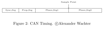
하나의 bit는 네 segment로 나뉩니다.
- Sync_Seg: node가 Sync_Seg edge에서 동기화하며 항상 time quantum 하나 길이입니다.
- Prop_Seg: bus의 signal propagation delay와 transceiver·node의 다른 delay를 나타냅니다.
- Phase_Seg1·Phase_Seg2: sampling point를 정하며 bit는 Phase_Seg1 끝에서 sample됩니다.
Bitrate는 time quantum의 시간과 위 segment 값으로 계산합니다. Bit 길이는 Sync_Seg + Prop_Seg + Phase_Seg1 + Phase_Seg2의 합에 time quantum 하나의 시간을 곱한 값이고, bitrate는 bit 하나 길이의 역수입니다.
Bit는 Phase_Seg1과 Phase_Seg2 사이의 sampling point에서 sample되므로 사용자가 이 parameter를 선택해야 합니다. CiA는 bit의 87.5% 지점으로 설정하기를 권장합니다.
Resynchronization Jump Width(SJW)는 resynchronization이 필요할 때 sampling point를 이동할 수 있는 time quantum 수를 정의합니다.
SJW, bitrate, sampling point 또는 bitrate와 Prop_Seg·Phase_Seg1·Phase_Seg2 timing parameter는 처음에 devicetree에서 설정하고 runtime에는 timing API로 변경할 수 있습니다.
CAN은 node address 대신 frame을 식별하는 identifier를 사용합니다. Standard/Basic Frame은 11-bit, Extended Frame은 29-bit identifier를 쓰며 Zephyr CAN API는 둘을 동시에 지원합니다.
CAN frame은 dominant Start Of Frame bit로 시작한 뒤 arbitration phase에서 identifier를 보냅니다. 이 구간에는 write collision이 허용되며 dominant bit가 recessive bit를 덮어써 해결됩니다. 각 node는 bus를 monitor하다 자기 transmission이 덮이면 중단하므로 숫자가 낮은 identifier가 높은 identifier보다 우선합니다.
Filter는 해당 node가 관심 있는 identifier를 whitelist하며 어떤 filter에도 맞지 않는 identifier는 무시합니다. Exact match 또는 identifier 일부를 mask로 비교할 수 있습니다. Standard identifier의 11bit, extended identifier의 29bit가 모두 1인 mask는 완전히 일치해야 하고, mask에서 0인 bit는 비교에서 무시됩니다. Hardware filter 수는 보통 제한되며 memory 절약을 위해 Kconfig에서도 제한합니다.
Transmission 중 잘못된 frame을 감지하면 node가 현재 frame 일부를 error frame으로 덮습니다. Controller 상태에 따라 error-passive 또는 error-active frame입니다. Error-active controller는 stuffing rule을 위반하는 dominant bit 6개를 연속 전송해 모든 node가 오류를 감지하게 하고 sender는 곧바로 frame을 다시 보낼 수 있습니다.
초기화된 node는 Error-active, Error-passive, Bus-off 중 한 상태입니다.
- 초기화 직후 error-active이며 active error frame, ACK, overload frame을 보낼 수 있습니다.
- 모든 node는 receive/transmit error counter를 가지며 둘 중 하나가 127을 넘으면 error-passive로 바뀌어 active error frame을 보낼 수 없습니다.
- Transmit error counter가 255까지 증가하면 bus-off가 되어 dominant bit를 전혀 보낼 수 없습니다. Bus-off node는 recessive bit 11개가 연속된 경우를 128회 받은 뒤 복구할 수 있습니다.
Zephyr는 Standard·Extended identifier, masking filter, loopback·silent mode, remote request를 지원합니다.
송신
0x123 standard identifier와 8-byte data를 보내는 기본 예입니다. Callback에 NULL을 넘기면 다른 node 하나 이상이 frame을 acknowledge하거나 error가 날 때까지 can_send()가 block됩니다. Timeout은 mailbox 획득에만 적용되며 transmission mailbox가 배정된 뒤에는 전송을 취소할 수 없습니다.
struct can_frame frame = {
        .flags = 0,
        .id = 0x123,
        .dlc = 8,
        .data = {1,2,3,4,5,6,7,8}
};
const struct device *const can_dev = DEVICE_DT_GET(DT_CHOSEN(zephyr_canbus));
int ret;

ret = can_send(can_dev, &frame, K_MSEC(100), NULL, NULL);
if (ret != 0) {
        LOG_ERR("Sending failed [%d]", ret);
}
0x1234567 extended identifier와 2-byte data를 보내는 예입니다. Message가 전송됐거나 error가 나면 callback이 호출됩니다. Timeout으로 K_FOREVER를 넘기면 frame에 mailbox가 배정되거나 error가 날 때까지 block되지만 앞 예처럼 실제 message 전송 완료까지 기다리지는 않습니다.
void tx_callback(const struct device *dev, int error, void *user_data)
{
        char *sender = (char *)user_data;

        if (error != 0) {
                LOG_ERR("Sending failed [%d]\nSender: %s\n", error, sender);
        }
}

int send_function(const struct device *can_dev)
{
        struct can_frame frame = {
                .flags = CAN_FRAME_IDE,
                .id = 0x1234567,
                .dlc = 2
        };

        frame.data[0] = 1;
        frame.data[1] = 2;

        return can_send(can_dev, &frame, K_FOREVER, tx_callback, "Sender 1");
}
수신
Frame은 filter와 일치할 때만 수신됩니다. 다음 예는 filter를 추가해 frame을 받는 방법입니다.
can_add_rx_filter()에 사용하는 receive callback이며 filter를 추가할 때 user data argument를 함께 전달합니다.
void rx_callback_function(const struct device *dev, struct can_frame *frame, void *user_data)
{
        ... do something with the frame ...
}
Callback filter는 가장 효율적이지만 가장 주의해야 하는 수신 방식입니다. Callback은 interrupt context에서 호출되므로 최대한 짧아야 하고 block하면 안 됩니다. Userspace context에서는 callback function을 추가할 수 없습니다. 다음 filter는 identifier 0x123과 정확히 일치합니다.
const struct can_filter my_filter = {
        .flags = 0U,
        .id = 0x123,
        .mask = CAN_STD_ID_MASK
};
int filter_id;
const struct device *const can_dev = DEVICE_DT_GET(DT_CHOSEN(zephyr_canbus));

filter_id = can_add_rx_filter(can_dev, rx_callback_function, callback_arg, &my_filter);
if (filter_id < 0) {
  LOG_ERR("Unable to add rx filter [%d]", filter_id);
}can_add_rx_filter_msgq()를 사용하면 frame을 synchronous하게 수신할 수 있고 userspace context에서도 호출할 수 있습니다. Message queue 크기는 예상 backlog만큼 잡아야 합니다. 다음 filter는 extended identifier 0x1234567과 정확히 일치합니다.
const struct can_filter my_filter = {
        .flags = CAN_FILTER_IDE,
        .id = 0x1234567,
        .mask = CAN_EXT_ID_MASK
};
CAN_MSGQ_DEFINE(my_can_msgq, 2);
struct can_frame rx_frame;
int filter_id;
const struct device *const can_dev = DEVICE_DT_GET(DT_CHOSEN(zephyr_canbus));

filter_id = can_add_rx_filter_msgq(can_dev, &my_can_msgq, &my_filter);
if (filter_id < 0) {
  LOG_ERR("Unable to add rx msgq [%d]", filter_id);
  return;
}

while (true) {
  k_msgq_get(&my_can_msgq, &rx_frame, K_FOREVER);
  ... do something with the frame ...
}can_remove_rx_filter()는 지정한 filter를 제거합니다.
can_remove_rx_filter(can_dev, filter_id);Bitrate 설정
Bitrate와 sampling point는 처음 runtime에 설정됩니다. Application에서 바꾸려면 can_set_timing()을 사용합니다. can_calc_timing()은 bitrate와 permille 단위 sampling point로 timing을 계산합니다. 다음은 bitrate 250k baud, sampling point 87.5%를 설정하는 예입니다.
struct can_timing timing;
const struct device *const can_dev = DEVICE_DT_GET(DT_CHOSEN(zephyr_canbus));
int ret;

ret = can_calc_timing(can_dev, &timing, 250000, 875);
if (ret > 0) {
  LOG_INF("Sample-Point error: %d", ret);
}

if (ret < 0) {
  LOG_ERR("Failed to calc a valid timing");
  return;
}

ret = can_stop(can_dev);
if (ret != 0) {
  LOG_ERR("Failed to stop CAN controller");
}

ret = can_set_timing(can_dev, &timing);
if (ret != 0) {
  LOG_ERR("Failed to set timing");
}

ret = can_start(can_dev);
if (ret != 0) {
  LOG_ERR("Failed to start CAN controller");
}
CAN FD controller의 data phase timing을 계산하고 설정하는 비슷한 API로 can_calc_timing_data()와 can_set_timing_data()가 있습니다.
SocketCAN
Zephyr는 CAN API의 BSD socket 구현인 SocketCAN도 지원합니다. 익숙한 BSD Socket API를 CAN에서 사용할 수 있고 여러 상위 CAN project가 사용하는 Linux SocketCAN 구현과 호환됩니다. Frame을 직접 전달하지 않고 network stack으로 routing하므로 computation과 memory overhead가 추가됩니다.
Sample
Zephyr CAN API를 보여 주는 build-ready sample은 CAN counter sample과 SocketCAN sample 두 개입니다.
CAN controller API reference
can_interface Doxygen group이 CAN controller의 공식 API reference를 제공합니다.
Source
출처
영어 원문에는 문단, 문서 지시문, 표, 코드, 코드 심벌, 경로를 그대로 보존했습니다.