Part 1
요약·해설
지원표 12행, 공식 이미지와 minicom·Segger build/flash 절차를 보존했습니다.
CPU
nRF52805 Arm
Radio
Bluetooth LE
Clock
Internal LF RC
Antenna
PCB · SMA
Part 2
접을 수 있는 영어 원문 전체
영어 원문 전체 펼치기
원문 SHA-256
903DB261A8BB13EF9A1E95633A14DB2E6245F7DCA5295C560462F495FC5D09C4
.. _we_ophelia1ev_nrf52805:

Ophelia-I EV NRF52805
#####################

Overview
********

The we_ophelia1ev_nrf52805 board is an evaluation board of the Ophelia-I radio module.
It provides support for the Nordic Semiconductor nRF52805 ARM CPU and
the following devices:

* CLOCK
* FLASH
* :abbr:`GPIO (General Purpose Input Output)`
* :abbr:`I2C (Inter-Integrated Circuit)`
* :abbr:`NVIC (Nested Vectored Interrupt Controller)`
* RADIO (Bluetooth Low Energy)
* :abbr:`RTC (nRF RTC System Clock)`
* Segger RTT (RTT Console)
* :abbr:`SPI (Serial Peripheral Interface)`
* :abbr:`UART (Universal asynchronous receiver-transmitter)`
* :abbr:`WDT (Watchdog Timer)`

.. figure:: ../../../../../../../boards/we/ophelia1ev/doc/img/we_ophelia1ev_nrf52805.jpg
     :align: center
     :alt: Ophelia-I EV

     Ophelia-I EV (Credit: Würth Elektronik)

Hardware
********

The Ophelia-I uses the internal low frequency RC oscillator
and provides the so called smart antenna connection, that allows
to choose between the module's integrated PCB antenna and an external
antenna that can be connected to the available SMA connector.

Supported Features
==================

The we_ophelia1ev_nrf52805 board configuration supports the following
hardware features:

+-----------+------------+----------------------+
| Interface | Controller | Driver/Component     |
+===========+============+======================+
| CLOCK     | on-chip    | clock_control        |
+-----------+------------+----------------------+
| FLASH     | on-chip    | flash                |
+-----------+------------+----------------------+
| GPIO      | on-chip    | gpio                 |
+-----------+------------+----------------------+
| I2C(M)    | on-chip    | i2c                  |
+-----------+------------+----------------------+
| MPU       | on-chip    | arch/arm             |
+-----------+------------+----------------------+
| NVIC      | on-chip    | arch/arm             |
+-----------+------------+----------------------+
| RADIO     | on-chip    | Bluetooth            |
+-----------+------------+----------------------+
| RTC       | on-chip    | system clock         |
+-----------+------------+----------------------+
| RTT       | Segger     | console              |
+-----------+------------+----------------------+
| SPI(M/S)  | on-chip    | spi                  |
+-----------+------------+----------------------+
| UART      | on-chip    | serial               |
+-----------+------------+----------------------+
| WDT       | on-chip    | watchdog             |
+-----------+------------+----------------------+

Programming and Debugging
*************************

Flashing
========

Follow the instructions in the :ref:`nordic_segger` page to install
and configure all the necessary software. Further information can be
found in :ref:`nordic_segger_flashing`. Then build and flash
applications as usual (see :ref:`build_an_application` and
:ref:`application_run` for more details).

Here is an example for the :ref:`hello_world` application.

First, run your favorite terminal program to listen for output.

.. code-block:: console

   $ minicom -D <tty_device> -b 115200

Replace :code:`<tty_device>` with the port where the board nRF52 DK
can be found. For example, under Linux, :code:`/dev/ttyACM0`.

Then build and flash the application in the usual way.

.. zephyr-app-commands::
   :zephyr-app: samples/hello_world
   :board: we_ophelia1ev/nrf52805
   :goals: build flash

Debugging
=========

Refer to the :ref:`nordic_segger` page to learn about debugging Nordic boards with a
Segger IC.

References
**********

.. target-notes::

.. _Ophelia-I radio module website: https://www.we-online.com/katalog/de/OPHELIA-I
.. _nRF52805 website: https://www.nordicsemi.com/Products/Low-power-short-range-wireless/nRF52805
Part 3
한국어 전문 번역
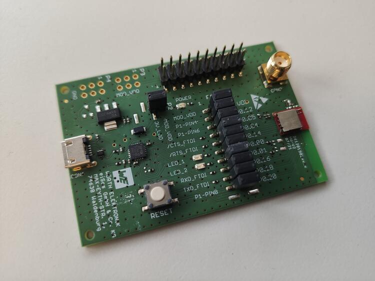
개요
we_ophelia1ev_nrf52805는 Ophelia-I radio module evaluation board입니다. Nordic Semiconductor nRF52805 ARM CPU와 clock, flash, GPIO, I2C, NVIC, Bluetooth Low Energy radio, RTC, Segger RTT, SPI, UART, watchdog를 지원합니다.
하드웨어
Ophelia-I는 internal low-frequency RC oscillator를 사용합니다. Smart antenna connection으로 module의 integrated PCB antenna와 SMA connector에 연결하는 external antenna 중 하나를 선택할 수 있습니다.
지원 기능
| Interface | Controller | Driver/Component |
|---|---|---|
| CLOCK | on-chip | clock_control |
| FLASH | on-chip | flash |
| GPIO | on-chip | gpio |
| I2C(M) | on-chip | i2c |
| MPU | on-chip | arch/arm |
| NVIC | on-chip | arch/arm |
| RADIO | on-chip | Bluetooth |
| RTC | on-chip | system clock |
| RTT | Segger | console |
| SPI(M/S) | on-chip | spi |
| UART | on-chip | serial |
| WDT | on-chip | watchdog |
Programming과 debugging
Flash
Zephyr Nordic Segger 안내에 따라 필요한 software를 설치·구성합니다. 먼저 terminal에서 115200 baud로 출력에 대기합니다. Linux port 예시는 /dev/ttyACM0입니다.
minicom -D <tty_device> -b 115200west build -b we_ophelia1ev/nrf52805 samples/hello_world
west flashDebug
Segger IC가 있는 Nordic board의 일반 debug 절차를 따릅니다.
참고 자료
Source
출처
영어 원문에는 문단, 문서 지시문, 표, 코드, 코드 심벌, 경로를 그대로 보존했습니다.