Part 1
요약·해설
공식 이미지 4개, connector 15개와 LED·button·통신 pin·Segger 절차를 보존했습니다.
CPU
nRF51822 Cortex-M0
Memory
256K flash · 32K RAM
USB-UART
CP2102
Revision
Rev3 QFAC
Part 2
접을 수 있는 영어 원문 전체
영어 원문 전체 펼치기
원문 SHA-256
8FD6995CA13201E32C85F78BBD38B8234A2F19FC614CCD724625DF5A2CDA52B7
.. _nrf51_ble400:

Waveshare BLE400
#################

Overview
********

BLE400 is a motherboard designed for BLE Bluetooth 2.4G Wireless Module. Used together with core board -- Core51822.

Supported Features
==================

Motherboard
------------

- Onboard battery holder, multi power supplies are available
- All the IOs are accessible for easy expansion
- Integrates CP2102 for debugging
- LEDs and user keys, compatible with other official boards, easy to use

Core board
----------

- Onboard chip: nRF51822
- Communication distance (open outdoor 1M data rate): 30m
- Frequency range: 2.4GHz
- Operating voltage: 2.0V ~ 3.6V
- Operating temperature: -40℃ ~ 85℃
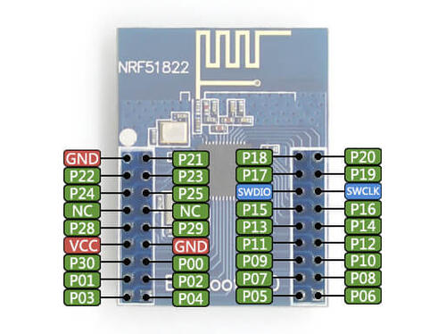
- Expansion pinheader: all the I/Os except P0.26 and P0.27
- Pinheader pitch: 2.00mm
- Antenna: onboard antenna

Features
========

- 2.4 GHz multiprotocol RF transceiver
- ARM® Cortex™-M0 32 bit processor
- 128 bit AES HW encryption
- 256kB flash & 32kB RAM
- Programmable Peripheral Interconnect (PPI)
- Digital interfaces: SPI, I2C, UART
- 10 bit ADC
- Programmable output power: -20 to +4 dBm
- Independent application development and protocol stack
- Fully compatible with NRF24L series
- Pinout compatible with NRF51xxx series
- Global separate power management
- Operating voltage: 1.8 V ~ 3.6 V

Revision History
================

Core board
----------

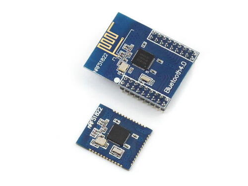
In June of 2015, Core51822 and its variant, Core51822 (B), upgraded the onboard chip to Rev3 (nRF51822_QFAC) that features 32kB RAM.

.. image:: ../../../../../../../boards/waveshare/nrf51_ble400/doc/img/Core51822-Compare.jpg
   :align: center
   :alt: Compare

Top: Core51822
Bottom: Core51822 (B)

Connections and IOs
====================

Motherboard
------------

.. image:: ../../../../../../../boards/waveshare/nrf51_ble400/doc/img/nrf51_ble400.jpg
   :align: center
   :alt: BLE400

1. Wireless module connector: for easily connecting modules like Core51822
2. MCU pins expansion connector
3. I2C interface
4. SPI interface
5. 5V/3.3V power input/output: usually used as power output, also common-grounding with other user board
6. USB connector: USB TO UART via onboard converter CP2102
7. Debugging interface
8. UART interface
9. Battery holder
10. User LEDs
11. User keys
12. Reset button
13. CP2102
14. USB TO UART jumper
15. LEDs & Keys jumper

Core board
----------

.. image:: ../../../../../../../boards/waveshare/nrf51_ble400/doc/img/Core51822-pin.jpg
   :align: center
   :alt: Core board pinout

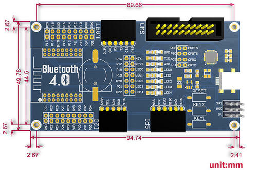
BLE400 dimensions
=================

.. image:: ../../../../../../../boards/waveshare/nrf51_ble400/doc/img/BLE400-size.jpg
   :align: center
   :alt: BLE400 size

Connections and IOs
===================

LED
---

* LED0 (red) = P0.18
* LED1 (red) = P0.19
* LED2 (red) = P0.20
* LED3 (red) = P0.21
* LED4 (red) = P0.22
* SUSPEND = SUSPEND
* RXD1 = P0.9
* TXD1 = P0.11

Push buttons
------------

* KEY1 = P0.16
* KEY2 = P0.17
* RESET = SWDIO

I2C
---

* SMBA = P0.02
* SCL = P0.01
* SDA = P0.00

SPI
---

* NSS = P0.30
* SCK = P0.25
* MOSI = P0.24
* MISO = P0.23

USART1
------

* RX = P0.05
* TX = P0.06
* CTS = P0.07
* RTS = P0.12

UART (USB)
----------

* RX = P0.9
* TX = P0.11
* CTS = P0.8
* RTS = P0.10

Programming and Debugging
*************************

Flashing
========

Follow the instructions in the :ref:`nordic_segger` page to install
and configure all the necessary software. Further information can be
found in :ref:`nordic_segger_flashing`. Then build and flash
applications as usual (see :ref:`build_an_application` and
:ref:`application_run` for more details).

Here is an example for the :ref:`hello_world` application.

First, run your favorite terminal program to listen for output.

.. code-block:: console

   $ minicom -D <tty_device> -b 115200

Replace :code:`<tty_device>` with the port where the board nRF51 DK
can be found. For example, under Linux, :code:`/dev/ttyACM0`.

Then build and flash the application in the usual way.

.. zephyr-app-commands::
   :zephyr-app: samples/hello_world
   :board: nrf51_ble400
   :goals: build flash

Debugging
=========

Refer to the :ref:`nordic_segger` page to learn about debugging Nordic boards with a
Segger IC.


Testing the LEDs and buttons in the nRF51 DK
********************************************

There are samples below that allow you to test that the buttons (switches) and LEDs on
the board are working properly with Zephyr:

- :zephyr:code-sample:`blinky`
- :zephyr:code-sample:`button`
- :zephyr:code-sample:`fade-led`
- :zephyr:code-sample:`multi-thread-blinky`

You can build and flash the examples to make sure Zephyr is running correctly on
your board. The button and LED definitions can be found in
:zephyr_file:`boards/waveshare/nrf51_ble400/nrf51_ble400.dts`.

References
**********

.. target-notes::

.. _nRF51 DK website: https://www.nordicsemi.com/Software-and-Tools/Development-Kits/nRF51-DK
.. _Nordic Semiconductor Infocenter: https://infocenter.nordicsemi.com
.. _Waveshare Wiki BLE400: https://www.waveshare.com/wiki/BLE400
.. _Waveshare WiKi Core51822: https://www.waveshare.com/wiki/Core51822
.. _User manual: https://www.waveshare.com/w/upload/b/b7/NRF51822-Eval-Kit-UserManual-EN.pdf
.. _Schematic: https://www.waveshare.com/w/upload/1/1b/BLE400-Schematic.pdf
.. _Code samples: https://www.waveshare.com/w/upload/5/53/NRF51822-Code.7z
.. _Core board schematics: https://www.waveshare.com/w/upload/5/57/Core51822-Schematic.pdf
Part 3
한국어 전문 번역
개요
BLE400은 BLE Bluetooth 2.4GHz wireless module용 motherboard이며 Core51822 core board와 함께 사용합니다.
지원 기능
Motherboard
- Onboard battery holder와 여러 power supply
- 확장하기 쉽도록 모든 I/O 접근 가능
- Debug용 CP2102 통합
- 다른 official board와 호환되는 LED와 user key
Core board
- Onboard nRF51822
- Open outdoor 1M data rate에서 통신 거리 30m
- 2.4GHz, 2.0~3.6V, -40~85°C
- P0.26과 P0.27을 제외한 모든 I/O의 expansion pin header
- 2.00mm pin header pitch
- Onboard antenna
기능
- 2.4GHz multiprotocol RF transceiver
- ARM Cortex-M0 32-bit processor
- 128-bit AES hardware encryption
- 256kB flash와 32kB RAM
- Programmable Peripheral Interconnect(PPI)
- SPI·I2C·UART digital interface
- 10-bit ADC
- -20~+4dBm programmable output
- Application과 protocol stack 독립 개발
- NRF24L 계열 완전 호환
- NRF51xxx-compatible pinout
- 분리된 global power management
- 1.8~3.6V 동작 전압
Revision history
2015년 6월 Core51822와 Core51822(B)는 32kB RAM의 Rev3 nRF51822_QFAC로 onboard chip을 upgrade했습니다.
연결과 I/O
Motherboard
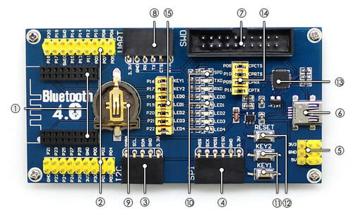
- 1. Core51822 같은 wireless module connector
- 2. MCU pin expansion connector
- 3. I2C interface
- 4. SPI interface
- 5. 5V/3.3V input/output와 common ground
- 6. CP2102 기반 USB-to-UART connector
- 7. Debug interface
- 8. UART interface
- 9. Battery holder
- 10. User LED
- 11. User key
- 12. Reset button
- 13. CP2102
- 14. USB-to-UART jumper
- 15. LED·key jumper
Core board
BLE400 dimension
연결과 I/O pin
LED
- LED0 red P0.18
- LED1 red P0.19
- LED2 red P0.20
- LED3 red P0.21
- LED4 red P0.22
- SUSPEND = SUSPEND
- RXD1 = P0.9
- TXD1 = P0.11
Push button
- KEY1 = P0.16
- KEY2 = P0.17
- RESET = SWDIO
I2C
- SMBA = P0.02
- SCL = P0.01
- SDA = P0.00
SPI
- NSS = P0.30
- SCK = P0.25
- MOSI = P0.24
- MISO = P0.23
USART1
- RX = P0.05
- TX = P0.06
- CTS = P0.07
- RTS = P0.12
UART(USB)
- RX = P0.9
- TX = P0.11
- CTS = P0.8
- RTS = P0.10
Programming과 debugging
Flash
Zephyr Nordic Segger 안내에 따라 software를 설치·구성합니다. 먼저 terminal에서 115200 baud로 출력에 대기합니다. Linux 예시는 /dev/ttyACM0입니다.
minicom -D <tty_device> -b 115200west build -b nrf51_ble400 samples/hello_world
west flashDebug
Segger IC를 사용하는 Nordic board debug 안내를 따릅니다.
nRF51 DK의 LED와 button 시험
- blinky
- button
- fade-led
- multi-thread-blinky
Button과 LED 정의는 boards/waveshare/nrf51_ble400/nrf51_ble400.dts에 있습니다.
참고 자료
Source
출처
영어 원문에는 문단, 문서 지시문, 표, 코드, 코드 심벌, 경로를 그대로 보존했습니다.