Part 1
요약·해설
표 3개 12행, 공식 이미지와 여섯 code block, M4 적재 성공·실패 log를 보존했습니다.
Cortex-A9 · Linux
Cortex-M4 · Zephyr
TCM · OCRAM · DDR
mqx_upload_on_m4SoloX
Part 2
접을 수 있는 영어 원문 전체
영어 원문 전체 펼치기
734661A38148608689A3BD5D270F4E064BCF0E4831919D9DC37A9727A023AB90
.. _udoo_neo_full:

UDOO Neo Full
#############

Overview
********

UDOO Neo Full is an open source Arduino Uno compatible single board computer.
It is equipped with an NXP |reg| i.MX 6SoloX hybrid multicore processor
composed of one ARM |reg| Cortex-A9 core running up to 1 GHz and one Cortex-M4
core running up to 227 MHz for high CPU performance and real-time response.
Zephyr was ported to run on the Cortex-M4 core only. In a future release, it
will also communicate with the Cortex-A9 core (running Linux) via OpenAMP.

.. figure:: ../../../../../../../boards/udoo/udoo_neo_full/doc/udoo_neo_full_mcimx6x_m4.jpg
   :align: center
   :alt: UDOO-Neo-Full

   UDOO Neo Full (Credit: udoo.org)

Hardware
********

- MCIMX6X MCU with a single Cortex-A9 (1 GHz) core and single Cortex-M4 (227 MHz) core

- Memory

  - 1 GB RAM
  - 128 KB OCRAM
  - 256 KB L2 cache (can be switched into OCRAM instead)
  - 16 KB OCRAM_S
  - 32 KB TCML
  - 32 KB TCMU
  - 32 KB CAAM (secure RAM)

- A9 Boot Devices

  - NOR flash
  - NAND flash
  - OneNAND flash
  - SD/MMC
  - Serial (I2C/SPI) NOR flash and EEPROM
  - QuadSPI (QSPI) flash

- Display

  - Micro HDMI connector
  - LVDS display connector
  - Touch (I2C signals)

- Multimedia

  - Integrated 2d/3d graphics controller
  - 8-bit parallel interface for analog camera supporting NTSC and PAL
  - HDMI audio transmitter
  - S/PDIF
  - I2S

- Connectivity

  - USB 2.0 Type A port
  - USB OTG (micro-AB connector)
  - 10/100 Mbit/s Ethernet PHY
  - Wi-Fi 802.11 b/g/n
  - Bluetooth 4.0 Low Energy
  - 3x UART ports
  - 2x CAN Bus interfaces
  - 8x PWM signals
  - 3x I2C interface
  - 1x SPI interface
  - 6x multiplexable signals
  - 32x GPIO (A9)
  - 22x GPIO (M4)

- Other

  - MicroSD card slot (8-bit SDIO interface)
  - Power status LED (green)
  - 2x user LED (red and orange)

- Power

  - 5 V DC Micro USB
  - 6-15 V DC jack
  - RTC battery connector

- Debug

  - pads for soldering of JTAG 14-pin connector

- Sensor

  - 3-Axis Accelerometer
  - 3-Axis Magnetometer
  - 3-Axis Digital Gyroscope
  - 1x Sensor Snap-In I2C connector

- Expansion port

  - Arduino interface

For more information about the MCIMX6X SoC and UDOO Neo Full board,
see these references:

- `NXP i.MX 6SoloX Website`_
- `NXP i.MX 6SoloX Datasheet`_
- `NXP i.MX 6SoloX Reference Manual`_
- `UDOO Neo Website`_
- `UDOO Neo Getting Started`_
- `UDOO Neo Documentation`_
- `UDOO Neo Datasheet`_
- `UDOO Neo Schematics`_

Supported Features
==================

The UDOO Neo Full board configuration supports the following hardware
features:

+-----------+------------+-------------------------------------+
| Interface | Controller | Driver/Component                    |
+===========+============+=====================================+
| NVIC      | on-chip    | nested vector interrupt controller  |
+-----------+------------+-------------------------------------+
| SYSTICK   | on-chip    | systick                             |
+-----------+------------+-------------------------------------+
| UART      | on-chip    | serial port-polling;                |
|           |            | serial port-interrupt               |
+-----------+------------+-------------------------------------+
| GPIO      | on-chip    | general purpose input/output        |
+-----------+------------+-------------------------------------+
| COUNTER   | on-chip    | counter                             |
+-----------+------------+-------------------------------------+

The default configuration can be found in the defconfig file:

	:zephyr_file:`boards/udoo/udoo_neo_full/udoo_neo_full_mcimx6x_m4_defconfig`

Other hardware features are not currently supported by the port.

Connections and IOs
===================

The UDOO Neo Full board was tested with the following pinmux
controller configuration.

+---------------+-----------------+---------------------------+
| Board Name    | SoC Name        | Usage                     |
+===============+=================+===========================+
| J4 RX         | UART5_RX_DATA   | UART Console              |
+---------------+-----------------+---------------------------+
| J4 TX         | UART5_TX_DATA   | UART Console              |
+---------------+-----------------+---------------------------+

System Clock
============

The MCIMX6X SoC is configured to use the 24 MHz external oscillator
on the board with the on-chip PLL to generate core clock.
PLL settings for M4 core are set via code running on the A9 core.

Serial Port
===========

The MCIMX6X SoC has six UARTs. UART5 is configured for the M4 core and the
remaining are used by the A9 core or not used.

Programming and Debugging
*************************

The M4 core does not have a flash memory and is not provided a clock
at power-on-reset. Therefore it needs to be started by the A9 core.
The A9 core is responsible to load the M4 binary application into the RAM,
put the M4 in reset, set the M4 Program Counter and Stack Pointer, and get
the M4 out of reset. The A9 can perform these steps at the bootloader level
or after the Linux system has booted.

The M4 core can use up to 5 different RAMs (some other types of memory like
a secure RAM are not currently implemented in Zephyr).
These are the memory mappings for A9 and M4:

+------------+-----------------------+-----------------------+-----------------------+
| Region     | Cortex-A9             | Cortex-M4             | Size                  |
+============+=======================+=======================+=======================+
| TCML       | 0x007F8000-0x007FFFFF | 0x1FFF8000-0x1FFFFFFF |   32 KB               |
+------------+-----------------------+-----------------------+-----------------------+
| TCMU       | 0x00800000-0x00807FFF | 0x20000000-0x20007FFF |   32 KB               |
+------------+-----------------------+-----------------------+-----------------------+
| OCRAM_S    | 0x008F8000-0x008FBFFF | 0x208F8000-0x208FBFFF |   16 KB               |
+------------+-----------------------+-----------------------+-----------------------+
| OCRAM      | 0x00900000-0x0091FFFF | 0x20900000-0x2091FFFF |  128 KB               |
+------------+-----------------------+-----------------------+-----------------------+
| DDR        | 0x80000000-0xFFFFFFFF | 0x80000000-0xDFFFFFFF | 2048 MB (1536 for M4) |
+------------+-----------------------+-----------------------+-----------------------+

References
==========

- `NXP i.MX 6SoloX Reference Manual`_ Chapter 2 - Memory Maps

You have to choose which RAM will be used at compilation time. This configuration
is done in the file :zephyr_file:`boards/udoo/udoo_neo_full/udoo_neo_full_mcimx6x_m4.dts`.

If you want to have the code placed in the subregion of a memory, which will
likely be the case when using DDR, select "zephyr,flash=&flash" and set the
DT_FLASH_SIZE macro to determine the region size and DT_FLASH_ADDR to determine
the address where the region begins.

If you want to have the data placed in the subregion of a memory, which will
likely be the case when using DDR, select "zephyr,sram = &sram", which sets the
CONFIG_SRAM_SIZE macro to determine the region size and
CONFIG_SRAM_BASE_ADDRESS to determine the address where the region begins.

Otherwise set "zephyr,flash" and/or "zephyr,sram" to one of the predefined
regions:

.. code-block:: none

   "zephyr,flash"
   - &tcml
   - &ocram_s
   - &ocram
   - &ddr

   "zephyr,sram"
   - &tcmu
   - &ocram_s
   - &ocram
   - &ddr

Below you will find the instructions how a Linux user space application running
on the A9 core can be used to load and run Zephyr application on the M4 core.

The UDOOBuntu Linux distribution contains a `udooneo-m4uploader`_ utility,
but its purpose is to load UDOO Neo "Arduino-like" sketches, so it doesn't
work with Zephyr applications in most cases. The reason is that there is
an exchange of information between this utility and the program running on the
M4 core using hardcoded shared memory locations. The utility writes a flag which
is read by the program running on the M4 core. The program is then supposed to
end safely and write the status to the shared memory location for the main core.
The utility then loads the new application and reads its status from the shared
memory location to determine if it has successfully launched. Since this
functionality is specific for the UDOO Neo "Arduino-like" sketches, it is not
implemented in Zephyr. However Zephyr applications can support it on their own
if planned to be used along with the UDOOBuntu Linux running on the A9 core.
The udooneo-uploader utility calls another executable named
mqx_upload_on_m4SoloX which can be called directly to load Zephyr applications.
Copy the Zephyr binary image into the Linux filesystem and invoke the utility
as a root user:

.. code-block:: console

   mqx_upload_on_m4SoloX zephyr.bin

If the output looks like below, the mqx_upload_on_m4SoloX could not read
the status of the stopped application. This is expected if the previously
loaded application is not a UDOO Neo "Arduino-like" sketch and ignores the
shared memory communication:

.. code-block:: console

   UDOONeo - mqx_upload_on_m4SoloX 1.1.0
   UDOONeo - Waiting M4 Stop, m4TraceFlags: 00000000
   UDOONeo - Waiting M4 Stop, m4TraceFlags: 00000000
   UDOONeo - Waiting M4 Stop, m4TraceFlags: 00000000
   UDOONeo - Waiting M4 Stop, m4TraceFlags: 00000000
   UDOONeo - Failed to Stop M4 sketch: reboot system !

In such situation, the mqx_upload_on_m4SoloX utility has reset the trace flags,
so it will succeed when called again. Then it can have this output below:

.. code-block:: console

   UDOONeo - mqx_upload_on_m4SoloX 1.1.0
   UDOONeo - FILENAME = zephyr.bin; loadaddr = 0x84000000
   UDOONeo - start - end (0x84000000 - 0x84080000)
   UDOONeo - Waiting M4 Run, m4TraceFlags: 000001E0
   UDOONeo - M4 sketch is running

Or the one below, if the utility cannot read the status flag that the M4 core
applications has started. It can be ignored as the application should be
running, the utility just doesn't know it:

.. code-block:: console

   UDOONeo - mqx_upload_on_m4SoloX 1.1.0
   UDOONeo - FILENAME = zephyr.bin; loadaddr = 0x84000000
   UDOONeo - start - end (0x84000000 - 0x84080000)
   UDOONeo - Waiting M4 Run, m4TraceFlags: 00000000
   UDOONeo - Waiting M4 Run, m4TraceFlags: 00000000
   UDOONeo - Waiting M4 Run, m4TraceFlags: 00000000
   UDOONeo - Waiting M4 Run, m4TraceFlags: 00000000
   UDOONeo - Failed to Start M4 sketch: reboot system !

The stack pointer and the program counter values are read from the binary.
The memory address where binary will be placed is calculated from the program
counter as its value aligned to 64 KB down, or it can be provided as a second
command line argument:

.. code-block:: console

   mqx_upload_on_m4SoloX zephyr.bin 0x84000000

It is necessary to provide the address if the binary is copied into a memory
region which has different mapping between the A9 and the M4 core. The address
calculated from the stack pointer value in the binary file would be wrong.

It is possible to modify the mqx_upload_on_m4SoloX utility source code
to not exchange the information with the M4 core application using shared
memory.

It is also possible to use the `imx-m4fwloader`_ utility to load the M4 core
application.

One option applicable in UDOOBuntu Linux is to copy the binary file into the
file /var/opt/m4/m4last.fw in the Linux filesystem. The next time the system is
booted, Das U-Boot will load it from there.

Another option is to directly use Das U-Boot to load the code.

Debugging
=========

The UDOO Neo Full board includes pads for soldering the 14-pin JTAG
connector. Zephyr applications running on the M4 core have only been
tested by observing UART console output.

References
==========

.. target-notes::

.. _UDOO Neo Website:
   https://www.udoo.org/udoo-neo/

.. _UDOO Neo Getting Started:
   https://www.udoo.org/get-started-neo/

.. _UDOO Neo Documentation:
   https://www.udoo.org/docs-neo

.. _UDOO Neo Datasheet:
   https://www.udoo.org/download/files/datasheets/datasheet_udoo_neo.pdf

.. _UDOO Neo Schematics:
   https://www.udoo.org/download/files/schematics/UDOO_NEO_schematics.pdf

.. _Udoo Neo Linux or Android Images for the A9 Core:
   https://www.udoo.org/downloads/

.. _udooneo-m4uploader:
   https://github.com/ektor5/udooneo-m4uploader

.. _imx-m4fwloader:
   https://github.com/codeauroraforum/imx-m4fwloader

.. _NXP i.MX 6SoloX Website:
   https://www.nxp.com/products/processors-and-microcontrollers/applications-processors/i.mx-applications-processors/i.mx-6-processors/i.mx-6solox-processors-heterogeneous-processing-with-arm-cortex-a9-and-cortex-m4-cores:i.MX6SX

.. _NXP i.MX 6SoloX Datasheet:
   https://www.nxp.com/docs/en/data-sheet/IMX6SXCEC.pdf

.. _NXP i.MX 6SoloX Reference Manual:
   https://www.nxp.com/docs/en/reference-manual/IMX6SXRM.pdf

.. _Loading Code on Cortex-M4 from Linux for the i.MX 6SoloX and i.MX 7Dual/7Solo Application Processors:
   https://www.nxp.com/docs/en/application-note/AN5317.pdf
Part 3
한국어 전문 번역
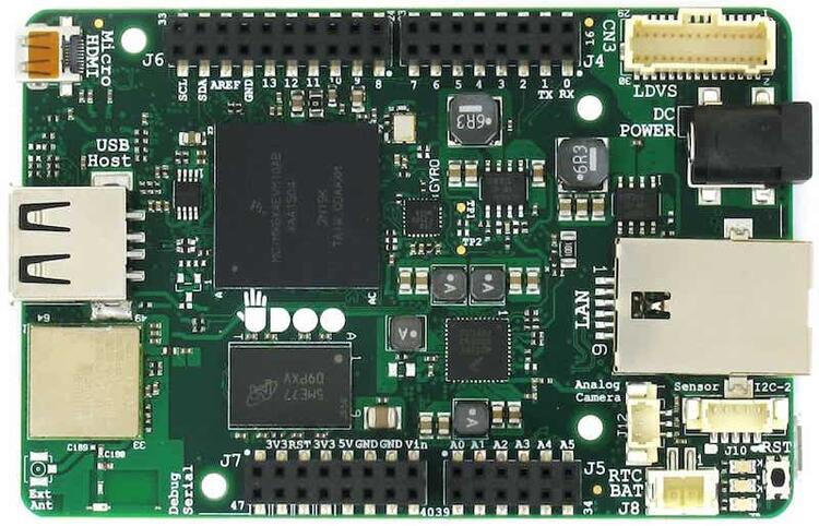
개요
UDOO Neo Full은 open source Arduino Uno compatible single-board computer입니다. NXP i.MX 6SoloX hybrid multicore processor에 최대 1GHz Cortex-A9 core 하나와 최대 227MHz Cortex-M4 core 하나가 있어 높은 CPU 성능과 실시간 응답을 함께 제공합니다. Zephyr는 Cortex-M4 core에서만 실행되도록 port됐으며 향후 Linux를 실행하는 Cortex-A9과 OpenAMP로 통신할 예정입니다.
하드웨어
- MCIMX6X MCU: Cortex-A9 1GHz core 1개와 Cortex-M4 227MHz core 1개
- Memory: 1GB RAM, 128KB OCRAM, OCRAM으로 전환 가능한 256KB L2 cache, 16KB OCRAM_S, 32KB TCML, 32KB TCMU, 32KB CAAM secure RAM
- A9 boot device: NOR, NAND, OneNAND, SD/MMC, serial I2C/SPI NOR·EEPROM, QuadSPI flash
- Display: Micro HDMI, LVDS display connector, I2C touch signal
- Multimedia: integrated 2D/3D graphics controller, NTSC/PAL analog camera용 8-bit parallel interface, HDMI audio transmitter, S/PDIF, I2S
- Connectivity: USB 2.0 Type A, USB OTG micro-AB, 10/100M Ethernet PHY, Wi-Fi 802.11 b/g/n, Bluetooth 4.0 LE, UART 3개, CAN 2개, PWM 8개, I2C 3개, SPI 1개, multiplexable signal 6개, A9 GPIO 32개, M4 GPIO 22개
- 기타: 8-bit SDIO MicroSD slot, green power LED, red·orange user LED
- Power: 5V DC Micro USB, 6-15V DC jack, RTC battery connector
- Debug: 14-pin JTAG connector 납땜 pad
- Sensor: 3-axis accelerometer, 3-axis magnetometer, 3-axis digital gyroscope, Sensor Snap-In I2C connector 1개
- Expansion: Arduino interface
MCIMX6X SoC와 board의 상세 정보는 아래 참고 자료에서 확인합니다.
지원 기능
| Interface | Controller | Driver/Component |
|---|---|---|
| NVIC | on-chip | nested vector interrupt controller |
| SYSTICK | on-chip | systick |
| UART | on-chip | serial port-polling; serial port-interrupt |
| GPIO | on-chip | general purpose input/output |
| COUNTER | on-chip | counter |
기본 설정은 boards/udoo/udoo_neo_full/udoo_neo_full_mcimx6x_m4_defconfig에 있습니다. 나머지 하드웨어 기능은 현재 이 port에서 지원하지 않습니다.
연결과 I/O
다음 pinmux controller configuration으로 시험했습니다.
| Board Name | SoC Name | Usage |
|---|---|---|
| J4 RX | UART5_RX_DATA | UART Console |
| J4 TX | UART5_TX_DATA | UART Console |
System clock
MCIMX6X SoC는 board의 24MHz external oscillator와 on-chip PLL로 core clock을 생성합니다. M4 core의 PLL 설정은 A9 core에서 실행되는 code가 구성합니다.
Serial port
MCIMX6X SoC에는 UART가 6개 있습니다. UART5는 M4 core용이고 나머지는 A9 core가 사용하거나 사용하지 않습니다.
Programming과 debugging
M4 core에는 flash memory가 없고 power-on-reset 때 clock도 공급되지 않으므로 A9 core가 시작해야 합니다. A9는 M4 binary를 RAM에 적재하고, M4를 reset에 두며, M4 Program Counter와 Stack Pointer를 설정한 뒤 reset에서 해제합니다. 이 절차는 bootloader 단계 또는 Linux boot 후 수행할 수 있습니다.
M4는 RAM 다섯 종류를 사용할 수 있습니다. Secure RAM 같은 일부 memory는 아직 Zephyr에 구현되지 않았습니다. A9과 M4의 mapping은 다음과 같습니다.
| Region | Cortex-A9 | Cortex-M4 | Size |
|---|---|---|---|
| TCML | 0x007F8000-0x007FFFFF | 0x1FFF8000-0x1FFFFFFF | 32 KB |
| TCMU | 0x00800000-0x00807FFF | 0x20000000-0x20007FFF | 32 KB |
| OCRAM_S | 0x008F8000-0x008FBFFF | 0x208F8000-0x208FBFFF | 16 KB |
| OCRAM | 0x00900000-0x0091FFFF | 0x20900000-0x2091FFFF | 128 KB |
| DDR | 0x80000000-0xFFFFFFFF | 0x80000000-0xDFFFFFFF | 2048 MB (M4용 1536 MB) |
근거는 i.MX 6SoloX Reference Manual chapter 2의 Memory Maps입니다.
Compile-time memory 선택
사용할 RAM은 compile 때 boards/udoo/udoo_neo_full/udoo_neo_full_mcimx6x_m4.dts에서 선택합니다. DDR처럼 memory의 일부 영역에 code를 둘 때는 zephyr,flash=&flash를 고르고 DT_FLASH_SIZE로 크기, DT_FLASH_ADDR로 시작 주소를 지정합니다. Data subregion은 zephyr,sram = &sram을 선택해 CONFIG_SRAM_SIZE와 CONFIG_SRAM_BASE_ADDRESS를 정합니다. 그렇지 않으면 다음 predefined region을 사용합니다.
"zephyr,flash"
- &tcml
- &ocram_s
- &ocram
- &ddr

"zephyr,sram"
- &tcmu
- &ocram_s
- &ocram
- &ddr
Linux에서 M4 application 적재
A9에서 실행되는 Linux user-space application으로 M4의 Zephyr application을 적재하고 실행할 수 있습니다. UDOOBuntu의 udooneo-m4uploader는 hardcoded shared-memory 위치로 M4의 Arduino-like sketch와 상태를 교환하기 때문에 일반 Zephyr application에는 대부분 동작하지 않습니다. Zephyr 쪽이 이 protocol을 직접 구현하면 함께 쓸 수 있습니다.
udooneo-m4uploader가 호출하는 mqx_upload_on_m4SoloX를 직접 사용합니다. Zephyr binary를 Linux filesystem에 복사하고 root로 실행합니다.
mqx_upload_on_m4SoloX zephyr.bin이전 M4 application이 shared-memory 통신을 무시하면 정지 상태를 읽지 못해 다음 실패가 나타날 수 있습니다.
UDOONeo - mqx_upload_on_m4SoloX 1.1.0
UDOONeo - Waiting M4 Stop, m4TraceFlags: 00000000
UDOONeo - Waiting M4 Stop, m4TraceFlags: 00000000
UDOONeo - Waiting M4 Stop, m4TraceFlags: 00000000
UDOONeo - Waiting M4 Stop, m4TraceFlags: 00000000
UDOONeo - Failed to Stop M4 sketch: reboot system !
이때 utility가 trace flag를 reset했으므로 다시 호출하면 성공할 수 있습니다.
UDOONeo - mqx_upload_on_m4SoloX 1.1.0
UDOONeo - FILENAME = zephyr.bin; loadaddr = 0x84000000
UDOONeo - start - end (0x84000000 - 0x84080000)
UDOONeo - Waiting M4 Run, m4TraceFlags: 000001E0
UDOONeo - M4 sketch is running
M4가 시작됐다는 flag를 읽지 못하면 다음 출력이 나올 수 있습니다. Application은 실행 중일 가능성이 있으므로 이 오류는 무시할 수 있습니다.
UDOONeo - mqx_upload_on_m4SoloX 1.1.0
UDOONeo - FILENAME = zephyr.bin; loadaddr = 0x84000000
UDOONeo - start - end (0x84000000 - 0x84080000)
UDOONeo - Waiting M4 Run, m4TraceFlags: 00000000
UDOONeo - Waiting M4 Run, m4TraceFlags: 00000000
UDOONeo - Waiting M4 Run, m4TraceFlags: 00000000
UDOONeo - Waiting M4 Run, m4TraceFlags: 00000000
UDOONeo - Failed to Start M4 sketch: reboot system !
Stack Pointer와 Program Counter는 binary에서 읽습니다. Binary 배치 주소는 Program Counter를 64KB 아래 경계로 정렬해 계산하거나 두 번째 command-line argument로 직접 지정합니다.
mqx_upload_on_m4SoloX zephyr.bin 0x84000000A9과 M4의 mapping이 다른 memory region에 binary를 복사했다면 주소를 반드시 지정해야 합니다. Binary의 Stack Pointer에서 계산한 주소는 잘못되기 때문입니다. Utility source를 수정해 shared-memory 상태 교환을 제거할 수도 있고, imx-m4fwloader로 M4 application을 적재할 수도 있습니다.
UDOOBuntu에서는 binary를 Linux의 /var/opt/m4/m4last.fw로 복사할 수 있습니다. 다음 boot에서 Das U-Boot가 이를 적재합니다. Das U-Boot를 직접 사용해 code를 적재하는 방법도 있습니다.
Debug
UDOO Neo Full에는 14-pin JTAG connector를 납땜할 pad가 있습니다. M4에서 실행되는 Zephyr application은 UART console 출력을 관찰하는 방식으로만 시험됐습니다.
참고 자료
Source
출처
영어 원문에는 문단, 문서 지시문, 표, 코드, 코드 심벌, 경로를 그대로 보존했습니다.