Part 1
요약·해설
지원표 12행, hardware 전체와 FMC/LTDC bus, CAN bridge·STMod+ 충돌을 보존했습니다.
MCU
STM32H7B3LI
Clock
280MHz
Memory
2MB / 1.4MB
Display
480×272 touch
Part 2
접을 수 있는 영어 원문 전체
영어 원문 전체 펼치기
원문 SHA-256
DB9ECECC32B6E021E47A63716A3AB56312481362D5B9C0DF1B0A6136F87A8BA6
.. _stm32h7b3i_dk_board:

ST STM32H7B3I Discovery kit
###########################

Overview
********

The STM32H7B3I-DK Discovery kit is a complete demonstration and development
platform for STMicroelectronics Arm® Cortex®-M7 core-based STM32H7B3LIH6QU
microcontroller.

The STM32H7B3I-DK Discovery kit is used as a reference design for user
application development before porting to the final product, thus simplifying
the application development.

The full range of hardware features available on the board helps users enhance
their application development by an evaluation of almost all peripherals (such as
USB OTG_HS, microSD, USART, FDCAN, audio DAC stereo with audio jack input and output,
camera, SDRAM, Octo-SPI Flash memory and RGB interface LCD with capacitive touch
panel). ARDUINO® Uno V3 connectors provide easy connection to extension shields or
daughterboards for specific applications.

Important board features include:

- STM32H7B3LIH6Q microcontroller featuring 2 Mbytes of Flash memory and 1.4 Mbyte of RAM in BGA225 package
- 4.3" (480x272 pixels) TFT color LCD module including a capacitive touch panel with RGB interface
- Wi-Fi |reg| module compliant with 802.11 b/g/n
- USB OTG HS
- Audio codec
- 512-Mbit Octo-SPI NOR Flash memory
- 128-Mbit SDRAM
- 2 user LEDs
- User and Reset push-buttons
- Fanout daughterboard
- 1x FDCAN
- Board connectors:
   - Camera (8 bit)
   - USB with Micro-AB
   - Stereo headset jack including analog microphone input
   - Audio jack for external speakers
   - microSD |trade| card
   - TAG-Connect 10-pin footprint
   - Arm |reg| Cortex |reg| 10-pin 1.27mm-pitch debug connector over STDC14 footprint
   - ARDUINO |reg| Uno V3 expansion connector
   - STMod+ expansion connector
   - Audio daughterboard expansion connector
   - External I2C expansion connector
- Flexible power-supply options:
   - ST-LINK USB VBUS, USB OTG HS connector, or external sources
- On-board STLINK-V3E debugger/programmer with USB re-enumeration capability

.. image:: ../../../../../../../boards/st/stm32h7b3i_dk/doc/img/stm32h7b3i_dk.jpg
     :align: center
     :alt: STM32H7B3I-DK

More information about the board can be found at the `STM32H7B3I-DK website`_.

Hardware
********

The STM32H7B3I Discovery kit provides the following hardware components:

- STM32H7B3LIH6Q in BGA225 package
- ARM |reg| 32-bit Cortex |reg| -M7 CPU with FPU
- 280 MHz max CPU frequency
- VDD from 1.62 V to 3.6 V
- 2 MB Flash
- ~1.4 Mbytes SRAM
- 32-bit timers(2)
- 16-bit timers(15)
- SPI(6)
- I2C(4)
- I2S (4)
- USART(5)
- UART(5)
- USB OTG Full Speed and High Speed(1)
- CAN FD(2)
- 2xSAI (serial audio interface)
- SPDIFRX interface(1)
- HDMI-CEC(1)
- Octo-SPI memory interfaces with on-the-fly decryption(2)
- 8- to 14-bit camera interface (1)
- 8-/16-bit parallel synchronous data input/output slave interface (PSSI)
- GPIO (up to 168) with external interrupt capability
- 16-bit ADC(2) with 24 channels / 3.6 MSPS
- 1x12-bit single-channel DAC + 1x12-bit dual-channel DAC
- True Random Number Generator (RNG)
- 5 DMA controllers
- LCD-TFT Controller with XGA resolution
- Chrom-ART graphical hardware Accelerator (DMA2D)
- Hardware JPEG Codec
- Chrom-GRC™ (GFXMMU)

More information about STM32H7B3 can be found here:

- `STM32H7A3/7B3 on www.st.com`_
- `STM32H7A3/7B3/7B0 reference manual`_
- `STM32H7B3xI datasheet`_

Supported Features
==================

The current Zephyr stm32h7b3i_dk board configuration supports the following hardware features:

+-----------+------------+-------------------------------------+
| Interface | Controller | Driver/Component                    |
+===========+============+=====================================+
| NVIC      | on-chip    | nested vector interrupt controller  |
+-----------+------------+-------------------------------------+
| UART      | on-chip    | serial port-polling;                |
|           |            | serial port-interrupt               |
+-----------+------------+-------------------------------------+
| PINMUX    | on-chip    | pinmux                              |
+-----------+------------+-------------------------------------+
| GPIO      | on-chip    | gpio                                |
+-----------+------------+-------------------------------------+
| I2C       | on-chip    | i2c                                 |
+-----------+------------+-------------------------------------+
| SDMMC     | on-chip    | disk access                         |
+-----------+------------+-------------------------------------+
| SPI       | on-chip    | spi                                 |
+-----------+------------+-------------------------------------+
| OSPI NOR  | on-chip    | off-chip flash                      |
+-----------+------------+-------------------------------------+
| FLASH     | on-chip    | flash memory                        |
+-----------+------------+-------------------------------------+
| FMC       | on-chip    | memc (SDRAM)                        |
+-----------+------------+-------------------------------------+
| LTDC      | on-chip    | display                             |
+-----------+------------+-------------------------------------+
| CANFD     | on-chip    | can                                 |
+-----------+------------+-------------------------------------+


Other hardware features have not been enabled yet for this board.

The default configuration can be found in the defconfig file:
:zephyr_file:`boards/st/stm32h7b3i_dk/stm32h7b3i_dk_defconfig`

Pin Mapping
===========

STM32H7B3I Discovery kit has 11 GPIO controllers. These controllers are responsible for pin muxing,
input/output, pull-up, etc.

For more details please refer to `STM32H7B3I-DK board User Manual`_.

Default Zephyr Peripheral Mapping:
----------------------------------

The STM32H7B3I Discovery kit features an Arduino Uno V3 connector. Board is
configured as follows

- UART_1 TX/RX : PA9/PA10 (ST-Link Virtual Port Com)
- UART_4 TX/RX : PH13/PH14 (Arduino Serial)
- I2C4 SCL/SDA : PD12/PD13 (Arduino I2C, Touchscreen FT5336 with PH2 Interrupt Pin)
- SPI2 SCK/MISO/MOSI/NSS : PA12/PB14/PB15/PI0 (Arduino SPI)
- LD1 : PG11
- LD2 : PG2
- USER_PB : PC13
- SDMMC D0/D1/D2/D3/CK/CMD/CD : PC8/PC9/PC10/PC11/PC12/PD2/PI8
- CANFD RX/TX/WAKE [#]_ : PA11/PA12/PH8
- FMC SDRAM :

    - D0-D15 : PD14/PD15/PD0/PD1/PE7/PE8/PE9/PE10/PE11/PE12/PE13/PE14/PE15/PD8/PD9/PD10
    - A0-A11 : PF0/PF1/PF2/PF3/PF4/PF5/PF12/PF13/PF14/PF15/PG0/PG1
    - A14/A15 : PG4/PG5
    - SDNRAS/SDNCAS : PF11/PG15
    - NBL0/NBL1 : PE0/PE1
    - SDCLK/SDNWE/SDCKE1/SDNE1 : PG8/PH5/PH7/PH6

- LTDC :

    - R0-R7 : PI15/PJ0/PJ1/PJ2/PJ3/PJ4/PJ5/PJ6
    - G0-G7 : PJ7/PJ8/PJ9/PJ10/PJ11/PK0/PK1/PK2
    - B0-B7 : PJ12/PJ13/PJ14/PJ15/PK3/PK4/PK5/PK6
    - DE/CLK/HSYNC/VSYNC : PK7/PI14/PI12/PI13


System Clock
============

The STM32H7B3I System Clock can be driven by an internal or external oscillator,
as well as by the main PLL clock. By default, the System clock is driven
by the PLL clock at 280MHz. PLL clock is fed by a 24MHz high speed external clock.

Serial Port
===========

The STM32H7B3I Discovery kit has up to 10 UARTs. The Zephyr console output is assigned
to UART1 which is connected to the onboard STLINK-V3E. Virtual COM port interface
default communication settings are 115200 8N1.


Programming and Debugging
*************************

Applications for the ``stm32h7b3i_dk`` board configuration can be built and
flashed in the usual way (see :ref:`build_an_application` and
:ref:`application_run` for more details).

Flashing
========

STM32H7B3I Discovery kit includes an STLINK-V3E embedded debug tool interface.
This interface is supported by the openocd version included in the Zephyr SDK.

Flashing may depend on the SoC option bytes configuration, which can be checked and
updated using `STM32CubeProgrammer`_.

Flashing an application to STM32H7B3I
-------------------------------------

First, connect the STM32H7B3I Discovery kit to your host computer using
the USB port to prepare it for flashing. Then build and flash your application.

Here is an example for the :ref:`hello_world` application.

.. zephyr-app-commands::
   :zephyr-app: samples/hello_world
   :board: stm32h7b3i_dk
   :goals: build flash

Run a serial host program to connect with your board:

.. code-block:: console

   $ minicom -D /dev/ttyACM0

You should see the following message on the console:

.. code-block:: console

   Hello World! arm

Debugging
=========

You can debug an application in the usual way.  Here is an example for the
:ref:`hello_world` application.

.. zephyr-app-commands::
   :zephyr-app: samples/hello_world
   :board: stm32h7b3i_dk
   :goals: debug


.. _STM32H7B3I-DK website:
   https://www.st.com/en/evaluation-tools/stm32h7b3i-dk.html

.. _STM32H7B3I-DK board User Manual:
   https://www.st.com/resource/en/user_manual/um2569-discovery-kit-with-stm32h7b3li-mcu-stmicroelectronics.pdf

.. _STM32H7A3/7B3 on www.st.com:
   https://www.st.com/en/microcontrollers-microprocessors/stm32h7a3-7b3.html

.. _STM32H7A3/7B3/7B0 reference manual:
   https://www.st.com/resource/en/reference_manual/rm0455-stm32h7a37b3-and-stm32h7b0-value-line-advanced-armbased-32bit-mcus-stmicroelectronics.pdf

.. _STM32H7B3xI datasheet:
   https://www.st.com/resource/en/datasheet/stm32h7b3ai.pdf

.. _STM32CubeProgrammer:
   https://www.st.com/en/development-tools/stm32cubeprog.html

.. _STM32H7B3I_DK board schematics:
   https://www.st.com/resource/en/schematic_pack/mb1332-h7b3i-c02_schematic.pdf

.. [#] To use CAN, solder bridges SB3, SB4 and SB5 need to be connected.
       Take note that CANFD pins are shared with STMOD+ connector (P1), so please check
       `STM32H7B3I_DK board schematics`_ for possible collisions if using that connector.
Part 3
한국어 전문 번역
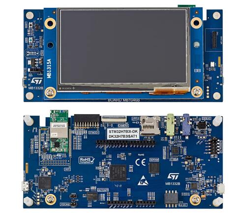
개요
STM32H7B3I-DK는 Cortex-M7 STM32H7B3LIH6QU의 reference development platform입니다. USB OTG HS, microSD, USART, FDCAN, stereo audio, camera, SDRAM, Octo-SPI, capacitive-touch RGB LCD를 평가하며 Arduino Uno V3를 제공합니다.
- BGA225 STM32H7B3LIH6Q: Flash 2MB, RAM 1.4MB
- capacitive touch 4.3-inch 480×272 RGB TFT
- 802.11 b/g/n Wi-Fi
- USB OTG HS
- audio codec
- 512Mbit Octo-SPI NOR Flash
- 128Mbit SDRAM
- user LED 2개
- USER·RESET button
- fanout daughterboard
- FDCAN 1개
- connector
- 8-bit camera
- Micro-AB USB
- analog microphone input stereo headset
- external speaker audio jack
- microSD
- TAG-Connect 10-pin
- STDC14 footprint Cortex 10-pin 1.27mm debug
- Arduino Uno V3
- STMod+
- audio daughterboard
- external I2C
- ST-LINK USB VBUS·USB OTG HS·external power
- USB re-enumeration STLINK-V3E
Hardware
- STM32H7B3LIH6Q, BGA225
- FPU Cortex-M7
- 최대 CPU 280MHz
- VDD 1.62~3.6V
- Flash 2MB
- SRAM 약 1.4MB
- 32-bit timer 2개
- 16-bit timer 15개
- SPI 6개
- I2C 4개
- I2S 4개
- USART 5개
- UART 5개
- USB OTG FS/HS 1개
- CAN FD 2개
- SAI 2개
- SPDIFRX 1개
- HDMI-CEC 1개
- on-the-fly decryption Octo-SPI 2개
- 8~14-bit camera 1개
- 8/16-bit PSSI
- external interrupt GPIO 최대 168개
- 24-channel 16-bit 3.6MSPS ADC 2개
- single-channel 12-bit DAC 1개 + dual-channel 12-bit DAC 1개
- TRNG
- DMA controller 5개
- XGA LCD-TFT controller
- Chrom-ART DMA2D
- hardware JPEG codec
- Chrom-GRC GFXMMU
Zephyr 지원 기능
| Interface | Controller | Driver/Component |
|---|---|---|
| NVIC | on-chip | nested vector interrupt controller |
| UART | on-chip | serial port-polling; serial port-interrupt |
| PINMUX | on-chip | pinmux |
| GPIO | on-chip | gpio |
| I2C | on-chip | i2c |
| SDMMC | on-chip | disk access |
| SPI | on-chip | spi |
| OSPI NOR | on-chip | off-chip flash |
| FLASH | on-chip | flash memory |
| FMC | on-chip | memc (SDRAM) |
| LTDC | on-chip | display |
| CANFD | on-chip | can |
기본 설정은 boards/st/stm32h7b3i_dk/stm32h7b3i_dk_defconfig입니다.
Pin mapping
GPIO controller 11개와 Arduino Uno V3를 사용합니다.
기본 Zephyr peripheral mapping
UART_1 TX/RX : PA9/PA10 (ST-Link Virtual Port Com)UART_4 TX/RX : PH13/PH14 (Arduino Serial)I2C4 SCL/SDA : PD12/PD13 (Arduino I2C, Touchscreen FT5336, PH2 IRQ)SPI2 SCK/MISO/MOSI/NSS : PA12/PB14/PB15/PI0 (Arduino SPI)LD1 : PG11LD2 : PG2USER_PB : PC13SDMMC D0/D1/D2/D3/CK/CMD/CD : PC8/PC9/PC10/PC11/PC12/PD2/PI8CANFD RX/TX/WAKE : PA11/PA12/PH8
FMC SDRAM
D0-D15 : PD14/PD15/PD0/PD1/PE7/PE8/PE9/PE10/PE11/PE12/PE13/PE14/PE15/PD8/PD9/PD10A0-A11 : PF0/PF1/PF2/PF3/PF4/PF5/PF12/PF13/PF14/PF15/PG0/PG1A14/A15 : PG4/PG5SDNRAS/SDNCAS : PF11/PG15NBL0/NBL1 : PE0/PE1SDCLK/SDNWE/SDCKE1/SDNE1 : PG8/PH5/PH7/PH6
LTDC
R0-R7 : PI15/PJ0/PJ1/PJ2/PJ3/PJ4/PJ5/PJ6G0-G7 : PJ7/PJ8/PJ9/PJ10/PJ11/PK0/PK1/PK2B0-B7 : PJ12/PJ13/PJ14/PJ15/PK3/PK4/PK5/PK6DE/CLK/HSYNC/VSYNC : PK7/PI14/PI12/PI13
Clock·serial
24MHz HSE가 PLL을 공급하며 기본 system clock은 280MHz입니다. UART는 최대 10개이며 console은 STLINK-V3E VCP의 UART1, 115200 8N1입니다.
Programming and debugging
OpenOCD가 STLINK-V3E를 지원하며 flash는 SoC option byte에 따라 달라질 수 있어 STM32CubeProgrammer로 확인합니다.
west build -b stm32h7b3i_dk samples/hello_world
west flash
$ minicom -D /dev/ttyACM0Hello World! armDebug
west build -b stm32h7b3i_dk samples/hello_world
west debug
참고 자료
Source
출처
영어 원문에는 문단, 문서 지시문, 표, 코드, 코드 심벌, 경로를 그대로 보존했습니다.