Part 1
요약·해설
지원표 10행, hardware 전체와 pin 10개, 216MHz VCP console·flash/debug 절을 전문 번역했습니다.
MCU
STM32F769NI
Clock
216MHz
Display
4-inch MIPI DSI
Network
Ethernet · PoE
Part 2
접을 수 있는 영어 원문 전체
영어 원문 전체 펼치기
원문 SHA-256
AE88F26CCB9F6386E6D1E0191EF5BB0697E75136F94CD7A3370BE9350DC6D1A9
.. _stm32f769i_disco_board:

ST STM32F769I Discovery
#######################

Overview
********

The discovery kit enables a wide diversity of applications taking benefit
from audio, multi-sensor support, graphics, security, security, video,
and high-speed connectivity features. Important board features include:

- STM32F769NIH6 microcontroller featuring 2 Mbytes of Flash memory and 512 Kbytes of RAM, in BGA216 package
- On-board ST-LINK/V2-1 supporting USB reenumeration capability
- USB ST-LINK functions: virtual COM port, mass storage, debug port
- Five power supply options:

  - ST LINK/V2-1
  - USB HS connector
  - 5 V from RJ45 (Power Over Ethernet)
  - 5 V from Arduino™ or external connector
  - USB charger

- 4-inch capacitive touch LCD display with MIPI-DSI connector
- SAI audio codec
- Two audio line jacks, one for input and one for output
- Stereo speaker outputs
- Four ST MEMS microphones on DFSDM inputs
- Two SPDIF RCA input and output connectors
- Two push-buttons (user and reset)
- 512-Mbit Quad-SPI Flash memory
- 128-Mbit SDRAM
- Connector for microSD card
- Wi-Fi or Ext-EEP daughterboard connector
- USB OTG HS with Micro-AB connector
- Ethernet connector compliant with IEEE-802.3-2002
- Power Over Ethernet based on IEEE 802.3af (Powered Device, 48 V to 5 V, 3 W)
- Power supply output for external applications: 3.3 V or 5 V
- Arduino Uno V3 connectors
- Comprehensive free software including a variety of examples, part of the STM32Cube package
- Supported by a wide choice of integrated development environments

.. image:: ../../../../../../../boards/st/stm32f769i_disco/doc/img/stm32f769i_disco.jpg
     :align: center
     :alt: STM32F769I-DISCO

More information about the board can be found at the `32F769I-DISCO website`_.

Hardware
********

The STM32F769I Discovery kit provides the following hardware components:

- STM32F769NIH6 in BGA216 package
- ARM |reg| 32-bit Cortex |reg| -M7 CPU with FPU
- 216 MHz max CPU frequency
- VDD from 1.7 V to 3.6 V
- 2 MB Flash
- 512 + 16 + 4 KB SRAM
- Flexible external memory controller with up to 32-bit data bus
- Dual mode Quad-SPI
- Chrom-ART Accelerator(DMA2D), graphical hardware accelerator enabling enhanced graphical user interface
- Hardware JPEG codec
- LCD-TFT controller supporting up to XGA resolution
- MIPI |reg|  DSI host controller supporting up to 720p 30Hz resolution
- 3x12-bit ADC with 24 channels
- 2x12-bit D/A converters
- DMA Controller
- General Purpose Timers (15)
- Watchdog Timers (2)
- I2C (4)
- USART/UART (8)
- SPI (6)
- SAI (2)
- CAN (3)
- SDMMC (2)
- SPDIFRX interface
- HDMI-CEC
- MDIO slave interface
- USB 2.0 full-speed device/host/OTG controller with on-chip PHY
- USB 2.0 high-speed/full-speed device/host/OTG controller with dedicated DMA, on-chip full-speed PHY and ULPI
- 10/100 Ethernet MAC with dedicated DMA: supports IEEE 1588v2 hardware, MII/RMII
- 8- to 14-bit camera interface up to 54 Mbyte/s
- True random number generator
- CRC calculation unit
- RTC: sub-second accuracy, hardware calendar
- 96-bit unique ID

More information about STM32F769NIH6 can be found here:

- `STM32F769NIH6 on www.st.com`_
- `STM32F76xxx reference manual`_

Supported Features
==================

The Zephyr stm32f769i_disco board configuration supports the following hardware features:

+-----------+------------+-------------------------------------+
| Interface | Controller | Driver/Component                    |
+===========+============+=====================================+
| NVIC      | on-chip    | nested vector interrupt controller  |
+-----------+------------+-------------------------------------+
| UART      | on-chip    | serial port-polling;                |
|           |            | serial port-interrupt               |
+-----------+------------+-------------------------------------+
| PINMUX    | on-chip    | pinmux                              |
+-----------+------------+-------------------------------------+
| GPIO      | on-chip    | gpio                                |
+-----------+------------+-------------------------------------+
| I2C       | on-chip    | i2c                                 |
+-----------+------------+-------------------------------------+
| SPI       | on-chip    | spi                                 |
+-----------+------------+-------------------------------------+
| ETHERNET  | on-chip    | Ethernet                            |
+-----------+------------+-------------------------------------+
| QSPI NOR  | on-chip    | flash                               |
+-----------+------------+-------------------------------------+
| FMC       | on-chip    | memc (SDRAM)                        |
+-----------+------------+-------------------------------------+
| TOUCH     | off-chip   | ft5336(FT6202)                      |
+-----------+------------+-------------------------------------+

Other hardware features are not yet supported on Zephyr porting.

The default configuration can be found in
:zephyr_file:`boards/st/stm32f769i_disco/stm32f769i_disco_defconfig`

Pin Mapping
===========

STM32F769I Discovery kit has 9 GPIO controllers. These controllers are responsible for pin muxing,
input/output, pull-up, etc.

For more details please refer to `32F769I-DISCO board User Manual`_.

Default Zephyr Peripheral Mapping:
----------------------------------

- UART_1 TX/RX : PA9/PA10 (ST-Link Virtual Port Com)
- UART_6 TX/RX : PC6/PC7 (Arduino Serial)
- I2C1 SCL/SDA : PB8/PB9 (Arduino I2C)
- I2C4 SCL/SDA : PD12/PB7 (Touchscreen FT6202, PI13 Interrupt Pin)
- SPI2 SCK/MISO/MOSI : PA12/PB14/PB15 (Arduino SPI)
- ETH : PA1, PA2, PA7, PC1, PC4, PC5, PG11, PG13, PG14
- LD1 : PJ13
- LD2 : PJ5
- LD3 : PA12
- LD4 : PD4

System Clock
============

The STM32F769I System Clock can be driven by an internal or external oscillator,
as well as by the main PLL clock. By default, the System clock is driven by the PLL
clock at 216MHz, driven by a 25MHz high speed external clock.

Serial Port
===========

The STM32F769I Discovery kit has up to 8 UARTs. The Zephyr console output is assigned to UART1
which connected to the onboard ST-LINK/V2 Virtual COM port interface. Default communication
settings are 115200 8N1.

Programming and Debugging
*************************

Applications for the ``stm32f769i_disco`` board configuration can be built and
flashed in the usual way (see :ref:`build_an_application` and
:ref:`application_run` for more details).

Flashing
========

STM32F769I Discovery kit includes an ST-LINK/V2 embedded debug tool interface.
This interface is supported by the openocd version included in the Zephyr SDK.

Flashing an application to STM32F769I
-------------------------------------------

First, connect the STM32F769I Discovery kit to your host computer using
the USB port to prepare it for flashing. Then build and flash your application.

Here is an example for the :ref:`hello_world` application.

.. zephyr-app-commands::
   :zephyr-app: samples/hello_world
   :board: stm32f769i_disco
   :goals: build flash

Run a serial host program to connect with your board:

.. code-block:: console

   $ minicom -D /dev/ttyACM0

You should see the following message on the console:

.. code-block:: console

   Hello World! arm

Debugging
=========

You can debug an application in the usual way.  Here is an example for the
:ref:`hello_world` application.

.. zephyr-app-commands::
   :zephyr-app: samples/hello_world
   :board: stm32f769i_disco
   :goals: debug


.. _32F769I-DISCO website:
   https://www.st.com/en/evaluation-tools/32f769idiscovery.html

.. _32F769I-DISCO board User Manual:
   https://www.st.com/resource/en/user_manual/dm00276557.pdf

.. _STM32F769NIH6 on www.st.com:
	https://www.st.com/content/st_com/en/products/microcontrollers/stm32-32-bit-arm-cortex-mcus/stm32-high-performance-mcus/stm32f7-series/stm32f7x9/stm32f769ni.html

.. _STM32F76xxx reference manual:
   https://www.st.com/resource/en/reference_manual/dm00224583.pdf
Part 3
한국어 전문 번역
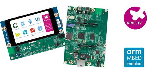
개요
STM32F769I Discovery kit는 audio, multi-sensor, graphics, security, video, high-speed connectivity application을 지원합니다. 원문은 security를 두 번 반복합니다.
- BGA216 STM32F769NIH6: Flash 2MB, RAM 512KB
- USB re-enumeration ST-LINK/V2-1
- virtual COM·mass storage·debug USB ST-LINK function
- 전원 방식 5개
- ST-LINK/V2-1
- USB HS
- RJ45 PoE 5V
- Arduino/external connector 5V
- USB charger
- MIPI-DSI connector 4-inch capacitive touch LCD
- SAI audio codec
- input·output audio line jack
- stereo speaker output
- DFSDM input ST MEMS microphone 4개
- SPDIF RCA input·output connector
- USER·RESET pushbutton
- 512Mbit Quad-SPI Flash
- 128Mbit SDRAM
- microSD connector
- Wi-Fi 또는 Ext-EEP daughterboard connector
- Micro-AB USB OTG HS
- IEEE-802.3-2002 Ethernet
- IEEE 802.3af PoE powered device: 48V→5V, 3W
- 외부 application용 3.3V·5V output
- Arduino Uno V3 connector
- STM32Cube example software
- 다양한 IDE 지원
Hardware
- STM32F769NIH6, BGA216
- FPU를 갖춘 ARM 32-bit Cortex-M7 CPU
- 최대 CPU 216MHz
- VDD 1.7~3.6V
- Flash 2MB
- SRAM 512+16+4KB
- 최대 32-bit data bus flexible external memory controller
- dual-mode Quad-SPI
- Chrom-ART Accelerator(DMA2D)
- hardware JPEG codec
- XGA LCD-TFT controller
- 720p 30Hz MIPI DSI host
- 24-channel 12-bit ADC 3개
- 12-bit DAC 2개
- DMA controller
- general-purpose timer 15개
- watchdog timer 2개
- I2C 4개
- USART/UART 8개
- SPI 6개
- SAI 2개
- CAN 3개
- SDMMC 2개
- SPDIFRX
- HDMI-CEC
- MDIO slave
- on-chip PHY USB 2.0 FS device/host/OTG
- dedicated DMA·on-chip FS PHY·ULPI USB 2.0 HS/FS device/host/OTG
- IEEE 1588v2·MII/RMII를 지원하는 10/100 Ethernet MAC
- 최대 54MB/s 8~14-bit camera interface
- true random number generator
- CRC unit
- sub-second hardware-calendar RTC
- 96-bit unique ID
Zephyr 지원 기능
| Interface | Controller | Driver/Component |
|---|---|---|
| NVIC | on-chip | nested vector interrupt controller |
| UART | on-chip | serial port-polling; serial port-interrupt |
| PINMUX | on-chip | pinmux |
| GPIO | on-chip | gpio |
| I2C | on-chip | i2c |
| SPI | on-chip | spi |
| ETHERNET | on-chip | Ethernet |
| QSPI NOR | on-chip | flash |
| FMC | on-chip | memc (SDRAM) |
| TOUCH | off-chip | ft5336(FT6202) |
표 밖 기능은 아직 지원하지 않습니다. 기본 설정은 boards/st/stm32f769i_disco/stm32f769i_disco_defconfig입니다.
Pin mapping
GPIO controller 9개가 pin muxing, input/output, pull-up 등을 담당합니다.
기본 Zephyr peripheral mapping
UART_1 TX/RX : PA9/PA10 (ST-Link Virtual Port Com)UART_6 TX/RX : PC6/PC7 (Arduino Serial)I2C1 SCL/SDA : PB8/PB9 (Arduino I2C)I2C4 SCL/SDA : PD12/PB7 (Touchscreen FT6202, PI13 Interrupt Pin)SPI2 SCK/MISO/MOSI : PA12/PB14/PB15 (Arduino SPI)ETH : PA1/PA2/PA7/PC1/PC4/PC5/PG11/PG13/PG14LD1 : PJ13LD2 : PJ5LD3 : PA12LD4 : PD4
System clock
기본 system clock은 25MHz high-speed external clock이 구동하는 PLL 216MHz입니다.
Serial port
UART는 최대 8개이며 Zephyr console은 on-board ST-LINK/V2 Virtual COM Port에 연결된 UART1, 기본 통신은 115200 8N1입니다.
Programming and debugging
Zephyr SDK OpenOCD가 지원하는 embedded ST-LINK/V2를 사용합니다.
west build -b stm32f769i_disco samples/hello_world
west flash
$ minicom -D /dev/ttyACM0Hello World! armDebug
west build -b stm32f769i_disco samples/hello_world
west debug
참고 자료
Source
출처
영어 원문에는 문단, 문서 지시문, 표, 코드, 코드 심벌, 경로를 그대로 보존했습니다.