Part 1
요약·해설
지원표 8행, 상세 L4 hardware, CAN transceiver 조건, 2개 SPI mapping과 page title/board target 차이를 보존합니다.
STM32L433RC
80MHz
256KB / 64KB
LPUART1
Part 2
접을 수 있는 영어 원문 전체
영어 원문 전체 펼치기
F3BDEEF71571039AC67393AFDCFBBE6EDC130F8C5C763933E5A60229D1E52A0F
.. _nucleo_l433rc_board:

ST Nucleo L433RC
################

Overview
********

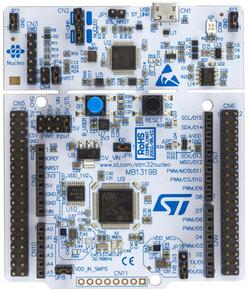
The Nucleo L433RC board features an ARM Cortex-M4 based STM32L433RC MCU
with a wide range of connectivity support and configurations. Here are
some highlights of the Nucleo L433RC board:

- STM32 microcontroller in LQFP64 package
- Arduino Uno V3 connectivity
- On-board ST-LINK/V2-1 debugger/programmer with SWD connector
- Flexible board power supply:

  - USB VBUS or external source(3.3V, 5V, 7 - 12V)
  - Power management access point

- Three LEDs: USB communication (LD1), power LED (LD3), user LED (LD4)
- One push-button: RESET

.. image:: ../../../../../../../boards/st/nucleo_l433rc_p/doc/img/nucleo_l433rc_p.jpg
  :align: center
  :alt: Nucleo L433RC

More information about the board can be found at the `Nucleo L433RC-P website`_.

Hardware
********

The STM32L433RC SoC provides the following hardware IPs:

- Ultra-low-power with FlexPowerControl (down to 28 nA Standby mode and 84
  |micro| A/MHz run mode)
- Core: ARM |reg| 32-bit Cortex |reg| -M4 CPU with FPU, frequency up to 80 MHz,
  100DMIPS/1.25DMIPS/MHz (Dhrystone 2.1)
- Clock Sources:

  - 32 kHz crystal oscillator for RTC (LSE)
  - Internal 16 MHz factory-trimmed RC ( |plusminus| 1%)
  - Internal low-power 32 kHz RC ( |plusminus| 5%)
  - Internal multispeed 100 kHz to 48 MHz oscillator, auto-trimmed by
    LSE (better than |plusminus| 0.25 % accuracy)
  - 2 PLLs for system clock, USB, audio, ADC

- RTC with HW calendar, alarms and calibration
- Up to 21 capacitive sensing channels: support touchkey, linear and rotary touch sensors
- 11x timers:

  - 1x 16-bit advanced motor-control
  - 1x 32-bit and 2x 16-bit general purpose
  - 2x 16-bit basic
  - 2x low-power 16-bit timers (available in Stop mode)
  - 2x watchdogs
  - SysTick timer

- Up to 83 fast I/Os, most 5 V-tolerant
- Memories

  - Up to 256 KB single bank Flash, proprietary code readout protection
  - 64 KB of SRAM including 16 KB with hardware parity check
  - Quad SPI memory interface

- Rich analog peripherals (independent supply)

  - 1x 12-bit ADC 5 MSPS, up to 16-bit with hardware oversampling, 200
    |micro| A/MSPS
  - 2x 12-bit DAC output channels, low-power sample and hold
  - 1x operational amplifiers with built-in PGA
  - 2x ultra-low-power comparators

- 17x communication interfaces

  - USB 2.0 full-speed crystal less solution with LPM and BCD
  - 1x SAI (serial audio interface)
  - 3x I2C FM+(1 Mbit/s), SMBus/PMBus
  - 4x USARTs (ISO 7816, LIN, IrDA, modem)
  - 1x LPUART (Stop 2 wake-up)
  - 3x SPIs (and 1x Quad SPI)
  - CAN (2.0B Active) and SDMMC interface
  - SWPMI single wire protocol master I/F
  - IRTIM (Infrared interface)

- 14-channel DMA controller
- True random number generator
- CRC calculation unit, 96-bit unique ID
- Development support: serial wire debug (SWD), JTAG, Embedded Trace Macrocell*


More information about STM32L433RC can be found here:

- `STM32L433RC on www.st.com`_
- `STM32L432 reference manual`_

Supported Features
==================

The Zephyr nucleo_l433rc_p board configuration supports the following hardware features:

+-----------+------------+-------------------------------------+
| Interface | Controller | Driver/Component                    |
+===========+============+=====================================+
| NVIC      | on-chip    | nested vector interrupt controller  |
+-----------+------------+-------------------------------------+
| UART      | on-chip    | serial port-polling;                |
|           |            | serial port-interrupt               |
+-----------+------------+-------------------------------------+
| PINMUX    | on-chip    | pinmux                              |
+-----------+------------+-------------------------------------+
| GPIO      | on-chip    | gpio                                |
+-----------+------------+-------------------------------------+
| I2C       | on-chip    | i2c                                 |
+-----------+------------+-------------------------------------+
| PWM       | on-chip    | pwm                                 |
+-----------+------------+-------------------------------------+
| CAN       | on-chip    | can                                 |
+-----------+------------+-------------------------------------+
| SPI       | on-chip    | spi                                 |
+-----------+------------+-------------------------------------+

.. note:: CAN feature requires CAN transceiver

Other hardware features are not yet supported on this Zephyr port.

The default configuration can be found in the defconfig file:
:zephyr_file:`boards/st/nucleo_l433rc_p/nucleo_l433rc_p_defconfig`


Connections and IOs
===================

Nucleo L433RC-P Board has 6 GPIO controllers. These controllers are responsible for pin muxing,
input/output, pull-up, etc.

Available pins:
---------------
.. image:: ../../../../../../../boards/st/nucleo_l433rc_p/doc/img/nucleo_l433rc_p_pinout.jpg
   :align: center
   :alt: Nucleo L433RC-P

For more details please refer to `ST Nucleo L433RC-P User Manual`_.

Default Zephyr Peripheral Mapping:
----------------------------------

- LPUART_1_TX : PA2
- LPUART_1_RX : PA3
- UART_1_TX : PA9
- UART_1_RX : PA10
- I2C_1_SCL : PB6
- I2C_1_SDA : PB7
- PWM_2_CH1 : PA0
- LD4 : PB13
- SPI_1: NSS/SCK/MISO/MOSI : PA4/PA5/PA6/PA7
- SPI_2: NSS/SCK/MISO/MOSI : PA11/PB13/PB14/PB15 (Arduino SPI)

System Clock
------------

Nucleo L433RC-P System Clock could be driven by internal or external oscillator,
as well as main PLL clock. By default System clock is driven by PLL clock at 80MHz,
driven by 16MHz high speed internal oscillator.

Serial Port
-----------

Nucleo L433RC-P board has 4 U(S)ARTs and 1 LPUART. The Zephyr console output is assigned
to LPUART1. Default settings are 115200 8N1.


Programming and Debugging
*************************

Applications for the ``nucleo_l433rc_p`` board configuration can be built and
flashed in the usual way (see :ref:`build_an_application` and
:ref:`application_run` for more details).

Flashing
========

Nucleo L433RC-P board includes an ST-LINK/V2-1 embedded debug tool
interface.  This interface is supported by the openocd version
included in the Zephyr SDK since v0.9.2.

Flashing an application to Nucleo L433RC-P
------------------------------------------

Connect the Nucleo L433RC-P to your host computer using the USB port,
then run a serial host program to connect with your Nucleo board.

.. code-block:: console

   $ picocom /dev/ttyACM0 -b 115200

Now build and flash an application. Here is an example for
:ref:`hello_world`.

.. zephyr-app-commands::
   :zephyr-app: samples/hello_world
   :board: nucleo_l433rc_p
   :goals: build flash

You should see the following message on the console:

.. code-block:: console

   $ Hello World! nucleo_l433rc_p


Debugging
=========

You can debug an application in the usual way.  Here is an example for the
:ref:`hello_world` application.

.. zephyr-app-commands::
   :zephyr-app: samples/hello_world
   :board: nucleo_l433rc_p
   :maybe-skip-config:
   :goals: debug

.. _Nucleo L433RC-P website:
   https://www.st.com/en/evaluation-tools/nucleo-l433rc-p.html

.. _ST Nucleo L433RC-P User Manual:
   https://www.st.com/resource/en/user_manual/dm00387966.pdf

.. _STM32L433RC on www.st.com:
   https://www.st.com/en/microcontrollers-microprocessors/stm32l433rc.html

.. _STM32L432 reference manual:
   https://www.st.com/resource/en/reference_manual/dm00151940.pdf
Part 3
한국어 전문 번역
개요
공식 page title은 ST Nucleo L433RC이지만 board configuration과 제품 링크는 nucleo_l433rc_p 및 L433RC-P를 사용합니다. Arm Cortex-M4 STM32L433RC board로 Arduino Uno V3를 지원합니다.
- LQFP64 STM32 MCU
- SWD가 있는 ST-LINK/V2-1
- USB VBUS 또는 외부 3.3V·5V·7~12V 전원과 power-management access point
- LD1 USB communication·LD3 power·LD4 user LED
- RESET button
Hardware
STM32L433RC가 제공하는 주요 hardware IP는 다음과 같습니다.
- FlexPowerControl: Standby 28nA, run 84µA/MHz
- FPU Cortex-M4 최대 80MHz, 100DMIPS·1.25DMIPS/MHz
- Crystal 4~48MHz, RTC LSE 32kHz, HSI 16MHz ±1%, LSI 32kHz ±5%, LSE auto-trim MSI 100kHz~48MHz, system·USB·audio·ADC용 PLL
- Calendar·alarm·calibration RTC
- Capacitive sensing channel 최대 21개
- Timer 11개: advanced motor 1개, 32-bit 1개, general 16-bit 2개, basic 16-bit 2개, low-power 2개, watchdog 2개, SysTick
- 대부분 5V tolerant인 fast I/O 최대 83개
- Single-bank 또는 dual-bank flash 최대 256KB, parity SRAM 16KB를 포함한 SRAM 64KB, Quad SPI
- 5MSPS 12-bit ADC 1개, 12-bit DAC channel 2개, PGA op amp 1개, comparator 2개
- Crystal-less USB 2.0 FS, SAI, I2C FM+ 3개, USART 4개, LPUART, SPI 3개+Quad SPI, CAN 2.0B, SDMMC, SWPMI, IRTIM
- 14-channel DMA, true RNG, CRC, 96-bit unique ID
- SWD·JTAG·ETM development support
Zephyr 지원 기능
| Interface | Controller | Driver/Component |
|---|---|---|
| NVIC | on-chip | nested vector interrupt controller |
| UART | on-chip | serial port-polling; serial port-interrupt |
| PINMUX | on-chip | pinmux |
| GPIO | on-chip | gpio |
| I2C | on-chip | i2c |
| PWM | on-chip | pwm |
| CAN | on-chip | can |
| SPI | on-chip | spi |
CAN에는 외부 transceiver가 필요합니다. 표 밖 기능은 아직 지원하지 않으며 기본 설정은 boards/st/nucleo_l433rc_p/nucleo_l433rc_p_defconfig입니다.
Connection과 I/O
GPIO controller 6개가 pin muxing, input/output, pull-up 등을 담당합니다.
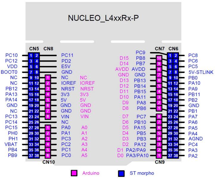
LPUART_1 TX/RX : PA2/PA3UART_1 TX/RX : PA9/PA10I2C_1 SCL/SDA : PB6/PB7PWM_2_CH1 : PA0LD4 : PB13SPI_1 NSS/SCK/MISO/MOSI : PA4/PA5/PA6/PA7SPI_2 NSS/SCK/MISO/MOSI : PA11/PB13/PB14/PB15(Arduino SPI)
System clock과 serial port
기본 system clock은 16MHz HSI가 구동하는 PLL의 80MHz입니다. U(S)ART 4개와 LPUART 1개 중 console은 LPUART1, 115200 8N1입니다.
ST-LINK/V2-1은 Zephyr SDK v0.9.2부터 포함된 OpenOCD가 지원합니다.
Programming and debugging
USB로 board를 연결하고 serial host를 연 뒤 hello_world를 build·flash합니다.
$ picocom /dev/ttyACM0 -b 115200west build -b nucleo_l433rc_p samples/hello_world
west flash$ Hello World! nucleo_l433rc_pDebugging
west build -b nucleo_l433rc_p samples/hello_world
west debug
참고 자료
Source
출처
영어 원문에는 문단, 문서 지시문, 표, 코드, 코드 심벌, 경로를 그대로 보존했습니다.