Part 1
요약·해설
지원표 18행, H743 hardware, Ethernet·CAN·SPI mapping, 96MHz clock, SB156·external CAN transceiver 및 OpenOCD 조건을 설명합니다.
STM32H743ZI
2MB
1MB
18 interfaces
Part 2
접을 수 있는 영어 원문 전체
영어 원문 전체 펼치기
7F75ED45D012BEBF514D82641226B7CA02CC4E8E96DE3188BE3FC3710542CCF4
.. _nucleo_h743zi_board:

ST Nucleo H743ZI
################

Overview
********

The STM32 Nucleo-144 boards offer combinations of performance and power that
provide an affordable and flexible way for users to build prototypes and try
out new concepts. For compatible boards, the SMPS (Switched-Mode Power Supply)
significantly reduces power consumption in Run mode.

The Arduino-compatible ST Zio connector expands functionality of the Nucleo
open development platform, with a wide choice of specialized Arduino* Uno V3
shields.

The STM32 Nucleo-144 board does not require any separate probe as it integrates
the ST-LINK/V2-1 debugger/programmer.

The STM32 Nucleo-144 board comes with the STM32 comprehensive free software
libraries and examples available with the STM32Cube MCU Package.

Key Features

- STM32 microcontroller in LQFP144 package
- Ethernet compliant with IEEE-802.3-2002 (depending on STM32 support)
- USB OTG or full-speed device (depending on STM32 support)
- 3 user LEDs
- 2 user and reset push-buttons
- 32.768 kHz crystal oscillator
- Board connectors:

 - USB with Micro-AB
 - SWD
 - Ethernet RJ45 (depending on STM32 support)
 - ST Zio connector including Arduino* Uno V3
 - ST morpho

- Flexible power-supply options: ST-LINK USB VBUS or external sources.
- On-board ST-LINK/V2-1 debugger/programmer with USB re-enumeration
- capability: mass storage, virtual COM port and debug port.
- Comprehensive free software libraries and examples available with the
  STM32Cube MCU package.
- Arm* Mbed Enabled* compliant (only for some Nucleo part numbers)

.. image:: ../../../../../../../boards/st/nucleo_h743zi/doc/img/nucleo_h743zi.jpg
   :align: center
   :alt: Nucleo H743ZI

More information about the board can be found at the `Nucleo H743ZI website`_.

Hardware
********

Nucleo H743ZI provides the following hardware components:

- STM32H743ZI in LQFP144 package
- ARM 32-bit Cortex-M7 CPU with FPU
- Chrom-ART Accelerator
- Hardware JPEG Codec
- 480 MHz max CPU frequency
- VDD from 1.62 V to 3.6 V
- 2 MB Flash
- 1 MB SRAM
- High-resolution timer (2.1 ns)
- 32-bit timers(2)
- 16-bit timers(12)
- SPI(6)
- I2C(4)
- I2S (3)
- USART(4)
- UART(4)
- USB OTG Full Speed and High Speed(1)
- USB OTG Full Speed(1)
- CAN FD(2)
- SAI(2)
- SPDIF_Rx(4)
- HDMI_CEC(1)
- Dual Mode Quad SPI(1)
- Camera Interface
- GPIO (up to 114) with external interrupt capability
- 16-bit ADC(3) with 36 channels / 3.6 MSPS
- 12-bit DAC with 2 channels(2)
- True Random Number Generator (RNG)
- 16-channel DMA
- LCD-TFT Controller with XGA resolution

Supported Features
==================

The Zephyr nucleo_h743zi board configuration supports the following hardware
features:

+-------------+------------+-------------------------------------+
| Interface   | Controller | Driver/Component                    |
+=============+============+=====================================+
| NVIC        | on-chip    | nested vector interrupt controller  |
+-------------+------------+-------------------------------------+
| UART        | on-chip    | serial port                         |
+-------------+------------+-------------------------------------+
| PINMUX      | on-chip    | pinmux                              |
+-------------+------------+-------------------------------------+
| GPIO        | on-chip    | gpio                                |
+-------------+------------+-------------------------------------+
| RTC         | on-chip    | counter                             |
+-------------+------------+-------------------------------------+
| I2C         | on-chip    | i2c                                 |
+-------------+------------+-------------------------------------+
| PWM         | on-chip    | pwm                                 |
+-------------+------------+-------------------------------------+
| ADC         | on-chip    | adc                                 |
+-------------+------------+-------------------------------------+
| DAC         | on-chip    | DAC Controller                      |
+-------------+------------+-------------------------------------+
| RNG         | on-chip    | True Random number generator        |
+-------------+------------+-------------------------------------+
| ETHERNET    | on-chip    | ethernet                            |
+-------------+------------+-------------------------------------+
| SPI         | on-chip    | spi                                 |
+-------------+------------+-------------------------------------+
| Backup SRAM | on-chip    | Backup SRAM                         |
+-------------+------------+-------------------------------------+
| WATCHDOG    | on-chip    | independent watchdog                |
+-------------+------------+-------------------------------------+
| USB         | on-chip    | usb_device                          |
+-------------+------------+-------------------------------------+
| CAN/CANFD   | on-chip    | canbus                              |
+-------------+------------+-------------------------------------+
| die-temp    | on-chip    | die temperature sensor              |
+-------------+------------+-------------------------------------+
| RTC         | on-chip    | rtc                                 |
+-------------+------------+-------------------------------------+

Other hardware features are not yet supported on this Zephyr port.

The default configuration can be found in the defconfig file:
:zephyr_file:`boards/st/nucleo_h743zi/nucleo_h743zi_defconfig`

For more details please refer to `STM32 Nucleo-144 board User Manual`_.

Default Zephyr Peripheral Mapping:
----------------------------------

The Nucleo H743ZI board features a ST Zio connector (extended Arduino Uno V3)
and a ST morpho connector. Board is configured as follows:

- UART_3 TX/RX : PD8/PD9 (ST-Link Virtual Port Com)
- USER_PB : PC13
- LD1 : PB0
- LD2 : PB7
- LD3 : PB14
- I2C : PB8, PB9
- ADC1_INP15 : PA3
- DAC1_OUT1 : PA4
- ETH : PA1, PA2, PA7, PB13, PC1, PC4, PC5, PG11, PG13
- SPI1 NSS/SCK/MISO/MOSI : PD14/PA5/PA6/PB5 (Arduino SPI)
- CAN/CANFD : PD0, PD1

System Clock
------------

Nucleo H743ZI System Clock could be driven by an internal or external
oscillator, as well as the main PLL clock. By default, the System clock is
driven by the PLL clock at 96MHz, driven by an 8MHz high-speed external clock.

Serial Port
-----------

Nucleo H743ZI board has 4 UARTs and 4 USARTs. The Zephyr console output is
assigned to UART3. Default settings are 115200 8N1.

Backup SRAM
-----------

In order to test backup SRAM you may want to disconnect VBAT from VDD. You can
do it by removing ``SB156`` jumper on the back side of the board.

CAN, CANFD
----------

Requires an external CAN or CANFD transceiver.

Programming and Debugging
*************************

Applications for the ``nucleo_h743zi`` board configuration can be built and
flashed in the usual way (see :ref:`build_an_application` and
:ref:`application_run` for more details).

.. note::

   If using OpenOCD you will need a recent development version as the last
   official release does not support H7 series yet. You can also choose the
   ``stm32cubeprogrammer`` runner.

Flashing
========

Nucleo H743ZI board includes an ST-LINK/V2-1 embedded debug tool interface.

Flashing an application to Nucleo H743ZI
----------------------------------------

Here is an example for the :ref:`hello_world` application.

Run a serial host program to connect with your Nucleo board.

.. code-block:: console

   $ minicom -b 115200 -D /dev/ttyACM0

Build and flash the application:

.. zephyr-app-commands::
   :zephyr-app: samples/hello_world
   :board: nucleo_h743zi
   :goals: build flash

You should see the following message on the console:

.. code-block:: console

   $ Hello World! nucleo_h743zi

Debugging
=========

You can debug an application in the usual way.  Here is an example for the
:ref:`hello_world` application.

.. zephyr-app-commands::
   :zephyr-app: samples/hello_world
   :board: nucleo_h743zi
   :maybe-skip-config:
   :goals: debug

.. _Nucleo H743ZI website:
   https://www.st.com/en/evaluation-tools/nucleo-h743zi.html

.. _STM32 Nucleo-144 board User Manual:
   https://www.st.com/resource/en/user_manual/dm00244518.pdf

.. _STM32H743ZI on www.st.com:
   https://www.st.com/content/st_com/en/products/microcontrollers-microprocessors/stm32-32-bit-arm-cortex-mcus/stm32-high-performance-mcus/stm32h7-series/stm32h743-753/stm32h743zi.html

.. _STM32H743 reference manual:
   https://www.st.com/resource/en/reference_manual/dm00314099.pdf
Part 3
한국어 전문 번역
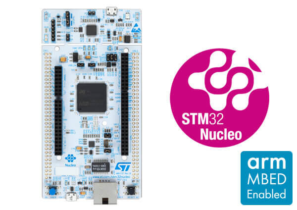
개요
STM32 Nucleo-144는 성능과 전력 조합을 선택해 prototype과 새 개념을 시험하는 경제적인 platform입니다. 호환 board의 SMPS는 Run-mode 전력을 줄이고 Arduino Uno V3 shield를 위한 ST Zio connector가 기능을 확장합니다. 별도 probe 없이 ST-LINK/V2-1과 STM32Cube MCU package library/example을 사용합니다.
주요 특징
- LQFP144 STM32 MCU
- STM32 지원 여부에 따른 IEEE 802.3-2002 Ethernet과 USB OTG/FS device
- User LED 3개, USER·RESET button, 32.768kHz crystal
- Micro-AB USB, SWD, Ethernet RJ45, Arduino Uno V3 포함 ST Zio, ST morpho
- ST-LINK USB VBUS 또는 external source 전원
- Mass storage·Virtual COM·debug port USB re-enumeration이 있는 ST-LINK/V2-1
- STM32Cube library/example, 일부 part number의 Arm Mbed Enabled compliance
Hardware
- LQFP144 STM32H743ZI, FPU Cortex-M7, 최대 480MHz, 1.62~3.6V
- Chrom-ART accelerator와 hardware JPEG codec
- Flash 2MB, SRAM 1MB
- 2.1ns high-resolution timer, 32-bit timer 2개, 16-bit timer 12개
- SPI 6개, I2C 4개, I2S 3개, USART 4개, UART 4개
- USB OTG FS+HS 1개와 USB OTG FS 1개, CAN FD 2개, SAI 2개, SPDIF_Rx 4개, HDMI_CEC
- Dual-mode Quad SPI, camera interface, external interrupt GPIO 최대 114개
- 36-channel 3.6MSPS 16-bit ADC 3개, 2-channel 12-bit DAC 2개
- True RNG, 16-channel DMA, XGA LCD-TFT controller
Zephyr 지원 기능
| Interface | Controller | Driver/Component |
|---|---|---|
| NVIC | on-chip | nested vector interrupt controller |
| UART | on-chip | serial port |
| PINMUX | on-chip | pinmux |
| GPIO | on-chip | gpio |
| RTC | on-chip | counter |
| I2C | on-chip | i2c |
| PWM | on-chip | pwm |
| ADC | on-chip | adc |
| DAC | on-chip | DAC Controller |
| RNG | on-chip | True Random number generator |
| ETHERNET | on-chip | ethernet |
| SPI | on-chip | spi |
| Backup SRAM | on-chip | Backup SRAM |
| WATCHDOG | on-chip | independent watchdog |
| USB | on-chip | usb_device |
| CAN/CANFD | on-chip | canbus |
| die-temp | on-chip | die temperature sensor |
| RTC | on-chip | rtc |
표 밖 기능은 아직 지원하지 않습니다. 기본 설정은 boards/st/nucleo_h743zi/nucleo_h743zi_defconfig이며 RTC는 counter와 rtc로 두 번 기재됩니다.
Connection과 I/O
UART_3 TX/RX : PD8/PD9(ST-Link Virtual COM)USER_PB : PC13LD1 : PB0,LD2 : PB7,LD3 : PB14I2C : PB8/PB9ADC1_INP15 : PA3,DAC1_OUT1 : PA4ETH : PA1/PA2/PA7/PB13/PC1/PC4/PC5/PG11/PG13SPI1 NSS/SCK/MISO/MOSI : PD14/PA5/PA6/PB5(Arduino SPI)CAN/CANFD : PD0/PD1
System clock·serial·backup SRAM
기본 system clock은 8MHz HSE가 구동하는 PLL의 96MHz입니다. UART 4개와 USART 4개 중 console은 UART3, 115200 8N1입니다. Backup SRAM 시험을 위해 VBAT를 VDD에서 분리하려면 board 뒤의 SB156 jumper를 제거합니다. CAN/CANFD에는 외부 transceiver가 필요합니다.
Programming and debugging
Onboard ST-LINK/V2-1을 사용합니다. 원문은 H7을 지원하지 않는 마지막 official release 대신 recent development OpenOCD를 쓰거나 stm32cubeprogrammer runner를 선택하라고 안내합니다.
$ minicom -b 115200 -D /dev/ttyACM0west build -b nucleo_h743zi samples/hello_world
west flash$ Hello World! nucleo_h743ziDebugging
west build -b nucleo_h743zi samples/hello_world
west debug
참고 자료
Source
출처
영어 원문에는 문단, 문서 지시문, 표, 코드, 코드 심벌, 경로를 그대로 보존했습니다.