Part 1
요약·해설
지원표 11행, UART·SPI·I2C·PWM·button·LED mapping과 blinky flash/debug workflow를 보존합니다.
STM32F103RB
11 interfaces
UART2 VCOM
ST-LINK/V2-1
Part 2
접을 수 있는 영어 원문 전체
영어 원문 전체 펼치기
188CAAB39ECE897F1EE0F1E3067F746EFFDF71D644ACF50E5B60E1151718C09A
.. _nucleo_f103rb_board:

ST Nucleo F103RB
################

Overview
********
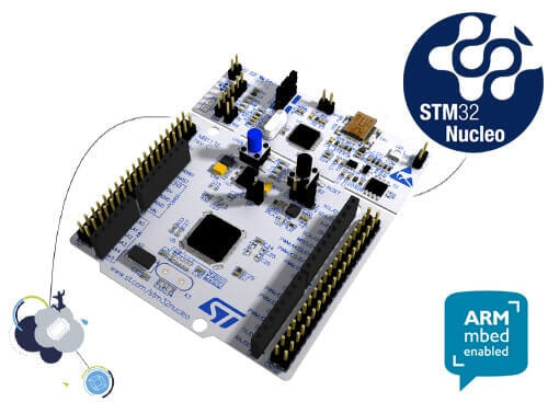
The STM32 Nucleo-64 development board with STM32F103RB MCU, supports Arduino and ST morpho connectivity.

The STM32 Nucleo board provides an affordable, and flexible way for users to try out new concepts,
and build prototypes with the STM32 microcontroller, choosing from the various
combinations of performance, power consumption, and features.

The Arduino* Uno V3 connectivity support and the ST morpho headers allow easy functionality
expansion of the STM32 Nucleo open development platform with a wide choice of
specialized shields.

The STM32 Nucleo board integrates the ST-LINK/V2-1 debugger and programmer.

The STM32 Nucleo board comes with the STM32 comprehensive software HAL library together
with various packaged software examples.

.. image:: ../../../../../../../boards/st/nucleo_f103rb/doc/img/nucleo_f103rb.jpg
   :align: center
   :alt: Nucleo F103RB

More information about the board can be found at the `Nucleo F103RB website`_.

Hardware
********
Nucleo F103RB provides the following hardware components:

- STM32 microcontroller in QFP64 package
- Two types of extension resources:

  - Arduino* Uno V3 connectivity
  - ST morpho extension pin headers for full access to all STM32 I/Os

- ARM* mbed*
- On-board ST-LINK/V2-1 debugger/programmer with SWD connector:

  - Selection-mode switch to use the kit as a standalone ST-LINK/V2-1

- Flexible board power supply:

  - USB VBUS or external source (3.3V, 5V, 7 - 12V)
  - Power management access point

- Three LEDs:

  - USB communication (LD1), user LED (LD2), power LED (LD3)

- Two push-buttons: USER and RESET
- USB re-enumeration capability. Three different interfaces supported on USB:

  - Virtual COM port
  - Mass storage
  - Debug port

- Support of wide choice of Integrated Development Environments (IDEs) including:

  - IAR
  - ARM Keil
  - GCC-based IDEs

More information about STM32F103RB can be found here:

- `STM32F103 reference manual`_
- `STM32F103 data sheet`_

Supported Features
==================

The Zephyr nucleo_f103rb board configuration supports the following hardware features:

+-----------+------------+-------------------------------------+
| Interface | Controller | Driver/Component                    |
+===========+============+=====================================+
| NVIC      | on-chip    | nested vector interrupt controller  |
+-----------+------------+-------------------------------------+
| UART      | on-chip    | serial port-polling;                |
|           |            | serial port-interrupt               |
+-----------+------------+-------------------------------------+
| PINMUX    | on-chip    | pinmux                              |
+-----------+------------+-------------------------------------+
| GPIO      | on-chip    | gpio                                |
+-----------+------------+-------------------------------------+
| CLOCK     | on-chip    | reset and clock control             |
+-----------+------------+-------------------------------------+
| FLASH     | on-chip    | flash memory                        |
+-----------+------------+-------------------------------------+
| WATCHDOG  | on-chip    | independent watchdog                |
+-----------+------------+-------------------------------------+
| ADC       | on-chip    | ADC Controller                      |
+-----------+------------+-------------------------------------+
| DMA       | on-chip    | Direct Memory Access                |
+-----------+------------+-------------------------------------+
| die-temp  | on-chip    | die temperature sensor              |
+-----------+------------+-------------------------------------+
| COUNTER   | on-chip    | rtc                                 |
+-----------+------------+-------------------------------------+

Other hardware features are not yet supported in this Zephyr port.

The default configuration can be found in
:zephyr_file:`boards/st/nucleo_f103rb/nucleo_f103rb_defconfig`

Connections and IOs
===================

Each of the GPIO pins can be configured by software as output (push-pull or open-drain), as
input (with or without pull-up or pull-down), or as peripheral alternate function. Most of the
GPIO pins are shared with digital or analog alternate functions. All GPIOs are high current
capable except for analog inputs.

Board connectors:
-----------------
.. image:: ../../../../../../../boards/st/nucleo_f103rb/doc/img/nucleo_f103rb_connectors.jpg
   :align: center
   :alt: Nucleo F103RB connectors

Default Zephyr Peripheral Mapping:
----------------------------------

- UART_1 TX/RX : PA9/PA10
- UART_2 TX/RX : PA2/PA3 (ST-Link Virtual COM Port)
- SPI1 NSS/SCK/MISO/MOSI : PB6/PA5/PA6/PA7 (Arduino SPI)
- SPI2 SCK/MISO/MOSI : PB12/PB13/PB14/PB15
- I2C1 SDA/SCL: PB9/PB8 (Arduino I2C)
- PWM1_CH1: PA8
- USER_PB : PC13
- LD1 : PA5

For more details please refer to `STM32 Nucleo-64 board User Manual`_.

Programming and Debugging
*************************

Applications for the ``nucleo_f103rb`` board configuration can be built and
flashed in the usual way (see :ref:`build_an_application` and
:ref:`application_run` for more details).

Flashing
========

Nucleo F103RB board includes an ST-LINK/V2-1 embedded debug tool interface.
This interface is supported by the openocd version included in the Zephyr SDK.

Flashing an application to Nucleo F103RB
----------------------------------------

Here is an example for the :zephyr:code-sample:`blinky` application.

.. zephyr-app-commands::
   :zephyr-app: samples/basic/blinky
   :board: nucleo_f103rb
   :goals: build flash

You will see the LED blinking every second.

Debugging
=========

You can debug an application in the usual way.  Here is an example for the
:zephyr:code-sample:`blinky` application.

.. zephyr-app-commands::
   :zephyr-app: samples/basic/blinky
   :board: nucleo_f103rb
   :maybe-skip-config:
   :goals: debug

References
**********

.. target-notes::

.. _Nucleo F103RB website:
   https://www.st.com/en/evaluation-tools/nucleo-f103rb.html

.. _STM32F103 reference manual:
   https://www.st.com/resource/en/reference_manual/cd00171190.pdf

.. _STM32F103 data sheet:
   https://www.st.com/resource/en/datasheet/stm32f103rb.pdf

.. _STM32 Nucleo-64 board User Manual:
   https://www.st.com/resource/en/user_manual/dm00105823.pdf
Part 3
한국어 전문 번역
개요
STM32F103RB MCU를 탑재한 STM32 Nucleo-64 development board로, Arduino와 ST morpho connectivity를 지원합니다. 성능·전력 소비·기능 조합을 선택하며 새 개념을 시험하고 STM32 prototype을 만들 수 있는 저렴하고 유연한 platform입니다. Arduino Uno V3 connector와 모든 STM32 I/O를 꺼내는 ST morpho header를 통해 다양한 shield로 기능을 확장할 수 있습니다.
Board에는 ST-LINK/V2-1 debugger/programmer, STM32 HAL library와 여러 packaged software example이 통합되어 있습니다.
Hardware
- QFP64 package의 STM32F103RB MCU
- Arduino Uno V3와 ST morpho extension
- Arm mbed 지원
- SWD connector가 있는 onboard ST-LINK/V2-1
- Kit를 standalone ST-LINK/V2-1로 쓰기 위한 selection-mode switch
- USB VBUS 또는 external 3.3V·5V·7~12V 전원과 power-management access point
- LD1 USB communication, LD2 user, LD3 power LED
- USER·RESET push-button
- Virtual COM port·mass storage·debug port를 제공하는 USB re-enumeration
- IAR·Arm Keil·GCC 기반 IDE 지원
MCU 상세 정보는 STM32F103 reference manual과 STM32F103RB datasheet에서 확인할 수 있습니다.
Zephyr 지원 기능
| Interface | Controller | Driver/Component |
|---|---|---|
| NVIC | on-chip | nested vector interrupt controller |
| UART | on-chip | serial port-polling; serial port-interrupt |
| PINMUX | on-chip | pinmux |
| GPIO | on-chip | gpio |
| CLOCK | on-chip | reset and clock control |
| FLASH | on-chip | flash memory |
| WATCHDOG | on-chip | independent watchdog |
| ADC | on-chip | ADC Controller |
| DMA | on-chip | Direct Memory Access |
| die-temp | on-chip | die temperature sensor |
| COUNTER | on-chip | rtc |
표에 없는 hardware 기능은 이 Zephyr port에서 아직 지원하지 않습니다. 기본 설정은 boards/st/nucleo_f103rb/nucleo_f103rb_defconfig에 있습니다.
Connection과 I/O
각 GPIO pin은 software로 push-pull/open-drain output, pull-up/down 유무를 포함한 input, peripheral alternate function으로 설정할 수 있습니다. 대부분은 digital 또는 analog alternate function과 공유되며 analog input을 제외한 모든 GPIO는 high-current capable입니다.
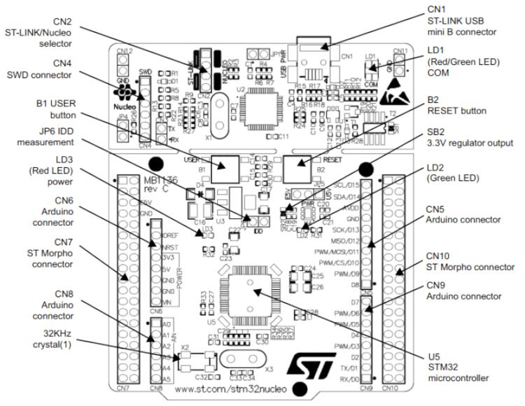
UART_1 TX/RX : PA9/PA10UART_2 TX/RX : PA2/PA3(ST-Link Virtual COM Port)SPI1 NSS/SCK/MISO/MOSI : PB6/PA5/PA6/PA7(Arduino SPI)SPI2 SCK/MISO/MOSI : PB12/PB13/PB14/PB15I2C1 SDA/SCL : PB9/PB8(Arduino I2C)PWM1_CH1 : PA8USER_PB : PC13LD1 : PA5
Programming and debugging
nucleo_f103rb application은 일반 Zephyr 절차로 build하고 flash합니다. Onboard ST-LINK/V2-1은 Zephyr SDK에 포함된 OpenOCD가 지원합니다.
Flashing
blinky sample을 build하고 flash하면 LED가 1초마다 깜박입니다.
west build -b nucleo_f103rb samples/basic/blinky
west flash
Debugging
다음 예시는 samples/basic/blinky application을 debug합니다.
west build -b nucleo_f103rb samples/basic/blinky
west debug
참고 자료
Source
출처
영어 원문에는 문단, 문서 지시문, 표, 코드, 코드 심벌, 경로를 그대로 보존했습니다.