Part 1
요약·해설
17개 지원 interface와 두 BOARD option, TF-M 준비·정리, TZEN/RDP/write-protection 해제 순서를 원문대로 보존합니다.
STM32U585AI
Cortex-M33
160MHz max
TrustZone · TF-M
Part 2
접을 수 있는 영어 원문 전체
영어 원문 전체 펼치기
F9AFB46032D1EBEE3438F706B8070AA05CCBA2D6C9EBB293A1FF0BD1172992DF
.. _b_u585i_iot02a_board:

ST B_U585I_IOT02A Discovery kit
###############################

Overview
********

The B_U585I_IOT02A Discovery kit features an ARM Cortex-M33 based STM32U585AI MCU
with a wide range of connectivity support and configurations. Here are
some highlights of the B_U585I_IOT02A Discovery kit:


- STM32U585AII6Q microcontroller featuring 2 Mbyte of Flash memory, 786 Kbytes of RAM in UFBGA169 package
- 512-Mbit octal-SPI Flash memory, 64-Mbit octal-SPI PSRAM, 256-Kbit I2C EEPROM
- USB FS, Sink and Source power, 2.5 W power capability
- 802.11 b/g/n compliant Wi-Fi® module from MXCHIP
- Bluetooth Low Energy from STMicroelectronics
- MEMS sensors from STMicroelectronics

  - 2 digital microphones
  - Relative humidity and temperature sensor
  - 3-axis magnetometer
  - 3D accelerometer and 3D gyroscope
  - Pressure sensor, 260-1260 hPa absolute digital output barometer
  - Time-of-flight and gesture-detection sensor
  - Ambient-light sensor

- 2 push-buttons (user and reset)
- 2 user LEDs

- Flexible power supply options:
    - ST-LINK/V3
    - USB Vbus
    - External sources


.. image:: ../../../../../../../boards/st/b_u585i_iot02a/doc/img/b-u585i-iot02a.jpg
     :align: center
     :alt: B_U585I_IOT02A Discovery kit

More information about the board can be found at the `B U585I IOT02A Discovery kit website`_.

Hardware
********

The STM32U585xx devices are an ultra-low-power microcontrollers family (STM32U5
Series) based on the high-performance Arm|reg| Cortex|reg|-M33 32-bit RISC core.
They operate at a frequency of up to 160 MHz.

- Ultra-low-power with FlexPowerControl (down to 300 nA Standby mode and 19.5 uA/MHz run mode)
- Core: ARM |reg| 32-bit Cortex |reg| -M33 CPU with TrustZone |reg| and FPU.
- Performance benchmark:

  - 1.5 DMPIS/MHz (Drystone 2.1)
  - 651 CoreMark |reg| (4.07 CoreMark |reg| /MHZ)

- Security and cryptography

  - Arm |reg|  TrustZone |reg| and securable I/Os memories and peripherals
  - Flexible life cycle scheme with RDP (readout protection) and password protected debug
  - Root of trust thanks to unique boot entry and secure hide protection area (HDP)
  - Secure Firmware Installation thanks to embedded Root Secure Services
  - Secure data storage with hardware unique key (HUK)
  - Secure Firmware Update support with TF-M
  - 2 AES coprocessors including one with DPA resistance
  - Public key accelerator, DPA resistant
  - On-the-fly decryption of Octo-SPI external memories
  - HASH hardware accelerator
  - Active tampers
  - True Random Number Generator NIST SP800-90B compliant
  - 96-bit unique ID
  - 512-byte One-Time Programmable for user data
  - Active tampers

- Clock management:

  - 4 to 50 MHz crystal oscillator
  - 32 kHz crystal oscillator for RTC (LSE)
  - Internal 16 MHz factory-trimmed RC ( |plusminus| 1%)
  - Internal low-power 32 kHz RC ( |plusminus| 5%)
  - 2 internal multispeed 100 kHz to 48 MHz oscillators, including one auto-trimmed by
    LSE (better than  |plusminus| 0.25 % accuracy)
  - 3 PLLs for system clock, USB, audio, ADC
  - Internal 48 MHz with clock recovery

- Power management

  - Embedded regulator (LDO)
  - Embedded SMPS step-down converter supporting switch on-the-fly and voltage scaling

- RTC with HW calendar and calibration
- Up to 136 fast I/Os, most 5 V-tolerant, up to 14 I/Os with independent supply down to 1.08 V
- Up to 24 capacitive sensing channels: support touchkey, linear and rotary touch sensors
- Up to 17 timers and 2 watchdogs

  - 2x 16-bit advanced motor-control
  - 2x 32-bit and 5 x 16-bit general purpose
  - 4x low-power 16-bit timers (available in Stop mode)
  - 2x watchdogs
  - 2x SysTick timer

- ART accelerator

  - 8-Kbyte instruction cache allowing 0-wait-state execution from Flash and
    external memories: up to 160 MHz, MPU, 240 DMIPS and DSP
  - 4-Kbyte data cache for external memories

- Memories

  - 2-Mbyte Flash memory with ECC, 2 banks read-while-write, including 512 Kbytes with 100 kcycles
  - 786-Kbyte SRAM with ECC OFF or 722-Kbyte SRAM including up to 322-Kbyte SRAM with ECC ON
  - External memory interface supporting SRAM, PSRAM, NOR, NAND and FRAM memories
  - 2 Octo-SPI memory interfaces

- Rich analog peripherals (independent supply)

  - 14-bit ADC 2.5-Msps, resolution up to 16 bits with hardware oversampling
  - 12-bit ADC 2.5-Msps, with hardware oversampling, autonomous in Stop 2 mode
  - 12-bit DAC, low-power sample and hold
  - 2 operational amplifiers with built-in PGA
  - 2 ultra-low-power comparators

- Up to 22 communication interfaces

  - USB Type-C / USB power delivery controller
  - USB OTG 2.0 full-speed controller
  - 2x SAIs (serial audio interface)
  - 4x I2C FM+(1 Mbit/s), SMBus/PMBus
  - 6x USARTs (ISO 7816, LIN, IrDA, modem)
  - 3x SPIs (5x SPIs with dual OCTOSPI in SPI mode)
  - 1x FDCAN
  - 2x SDMMC interface
  - 16- and 4-channel DMA controllers, functional in Stop mode
  - 1 multi-function digital filter (6 filters)+ 1 audio digital filter with
    sound-activity detection

- CRC calculation unit
- Development support: serial wire debug (SWD), JTAG, Embedded Trace Macrocell |trade|
- True Random Number Generator (RNG)

- Graphic features

  - Chrom-ART Accelerator (DMA2D) for enhanced graphic content creation
  - 1 digital camera interface

- Mathematical co-processor

 - CORDIC for trigonometric functions acceleration
 - FMAC (filter mathematical accelerator)


More information about STM32U585AI can be found here:

- `STM32U585 on www.st.com`_
- `STM32U585 reference manual`_


Supported Features
==================

The Zephyr b_u585i_iot02a board configuration supports the following hardware features:

+-----------+------------+-------------------------------------+
| Interface | Controller | Driver/Component                    |
+===========+============+=====================================+
| NVIC      | on-chip    | nested vector interrupt controller  |
+-----------+------------+-------------------------------------+
| UART      | on-chip    | serial port-polling;                |
|           |            | serial port-interrupt               |
+-----------+------------+-------------------------------------+
| PINMUX    | on-chip    | pinmux                              |
+-----------+------------+-------------------------------------+
| GPIO      | on-chip    | gpio                                |
+-----------+------------+-------------------------------------+
| RNG       | on-chip    | True Random number generator        |
+-----------+------------+-------------------------------------+
| I2C       | on-chip    | i2c                                 |
+-----------+------------+-------------------------------------+
| SPI       | on-chip    | spi                                 |
+-----------+------------+-------------------------------------+
| DAC       | on-chip    | dac                                 |
+-----------+------------+-------------------------------------+
| ADC       | on-chip    | adc                                 |
+-----------+------------+-------------------------------------+
| WATCHDOG  | on-chip    | independent watchdog                |
+-----------+------------+-------------------------------------+
| USB       | on-chip    | usb_device                          |
+-----------+------------+-------------------------------------+
| BKP SRAM  | on-chip    | Backup SRAM                         |
+-----------+------------+-------------------------------------+
| PWM       | on-chip    | pwm                                 |
| die-temp  | on-chip    | die temperature sensor              |
+-----------+------------+-------------------------------------+
| AES       | on-chip    | crypto                              |
+-----------+------------+-------------------------------------+
| RADIO     | STM32WB5MMG| Bluetooth Low Energy (BLE)          |
+-----------+------------+-------------------------------------+
| RTC       | on-chip    | rtc                                 |
+-----------+------------+-------------------------------------+

The default configuration can be found in the defconfig file:
:zephyr_file:`boards/st/b_u585i_iot02a/b_u585i_iot02a_defconfig`

Zephyr board options
====================

The STM32U585i is an SoC with Cortex-M33 architecture. Zephyr provides support
for building for both Secure and Non-Secure firmware.

The BOARD options are summarized below:

+-------------------------------+-------------------------------------------+
| BOARD                         | Description                               |
+===============================+===========================================+
| b_u585i_iot02a                | For building Trust Zone Disabled firmware |
+-------------------------------+-------------------------------------------+
| b_u585i_iot02a/stm32u585xx/ns | For building Non-Secure firmware          |
+-------------------------------+-------------------------------------------+

Here are the instructions to build Zephyr with a non-secure configuration,
using `tfm_ipc_` sample:

   .. code-block:: bash

      $ west build -b b_u585i_iot02a/stm32u585xx/ns samples/tfm_integration/tfm_ipc/

Once done, before flashing, you need to first run a generated script that
will set platform option bytes config and erase platform (among others,
option bit TZEN will be set).

   .. code-block:: bash

      $ ./build/tfm/api_ns/regression.sh
      $ west flash

Please note that, after having run a TFM sample on the board, you will need to
run `./build/tfm/api_ns/regression.sh` once more to clean up the board from secure
options and get back the platform back to a "normal" state and be able to run
usual, non-TFM, binaries.
Also note that, even then, TZEN will remain set, and you will need to use
STM32CubeProgrammer_ to disable it fully, if required.

Connections and IOs
===================

B_U585I_IOT02A Discovery kit has 9 GPIO controllers (from A to I). These controllers are responsible for pin muxing,
input/output, pull-up, etc.

For more details please refer to `B U585I IOT02A board User Manual`_.

Default Zephyr Peripheral Mapping:
----------------------------------

- UART_1 TX/RX : PA9/PA10 (ST-Link Virtual Port Com)
- LD1 : PH7
- LD2 : PH6
- user button : PC13
- SPI1 NSS/SCK/MISO/MOSI : PE12/P13/P14/P15 (Arduino SPI)
- I2C_1 SDA/SDL : PB9/PB8 (Arduino I2C)
- I2C_2 SDA/SDL : PH5/PH4
- DAC1 CH1 : PA4 (STMOD+1)
- ADC1_IN15 : PB0
- USB OTG : PA11/PA12
- PWM4 : CN14 PB6
- PWM3 : CN4 PE4

System Clock
------------

B_U585I_IOT02A Discovery System Clock could be driven by an internal or external oscillator,
as well as the main PLL clock. By default the System clock is driven by the PLL clock at 80MHz,
driven by 16MHz high speed internal oscillator.

Serial Port
-----------

B_U585I_IOT02A Discovery kit has 4 U(S)ARTs. The Zephyr console output is assigned to UART1.
Default settings are 115200 8N1.


Backup SRAM
-----------

In order to test backup SRAM you may want to disconnect VBAT from VDD. You can
do it by removing ``SB6`` jumper on the back side of the board.


Programming and Debugging
*************************

B_U585I_IOT02A Discovery kit includes an ST-LINK/V3 embedded debug tool interface.
This probe allows to flash the board using various tools.


Flashing
========

Board is configured to be flashed using west STM32CubeProgrammer runner.
Installation of `STM32CubeProgrammer`_ is then required to flash the board.

Alternatively, openocd (provided in Zephyr SDK), JLink and pyocd can also be
used to flash and debug the board if west is told to use it as runner,
using ``-r openocd``.

Connect the B_U585I_IOT02A Discovery kit to your host computer using the USB
port, then run a serial host program to connect with your Discovery
board. For example:

.. code-block:: console

   $ minicom -D /dev/ttyACM0

Then, build and flash in the usual way. Here is an example for the
:ref:`hello_world` application.

.. zephyr-app-commands::
   :zephyr-app: samples/hello_world
   :board: b_u585i_iot02a
   :goals: build flash

You should see the following message on the console:

.. code-block:: console

   Hello World! arm

Debugging
=========

Default flasher for this board is openocd. It could be used in the usual way.
Here is an example for the :zephyr:code-sample:`blinky` application.

.. zephyr-app-commands::
   :zephyr-app: samples/basic/blinky
   :board: b_u585i_iot02a
   :goals: debug

Disabling TrustZone |reg| on the board
======================================

If you have flashed a sample to the board that enables TrustZone, you will need
to disable it before you can flash and run a new non-TrustZone sample on the
board.

To disable TrustZone, it's necessary to change AT THE SAME TIME the ``TZEN``
and ``RDP`` bits. ``TZEN`` needs to get set from 1 to 0 and ``RDP``,
needs to be set from ``DC`` to ``AA`` (step 3 below).

This is docummented in the `AN5347, in section 9`_, "TrustZone deactivation".

However, it's possible that the ``RDP`` bit is not yet set to ``DC``, so you
first need to set it to ``DC`` (step 2).

Finally you need to set the "Write Protection 1 & 2" bytes properly, otherwise
some memory regions won't be erasable and mass erase will fail (step 4).

The following command sequence will fully deactivate TZ:

Step 1:

Ensure U23 BOOT0 switch is set to 1 (switch is on the left, assuming you read
"BOOT0" silkscreen label from left to right). You need to press "Reset" (B2 RST
switch) after changing the switch to make the change effective.

Step 2:

.. code-block:: console

   $ STM32_Programmer_CLI -c port=/dev/ttyACM0 -ob rdp=0xDC

Step 3:

.. code-block:: console

   $ STM32_Programmer_CLI -c port=/dev/ttyACM0 -tzenreg

Step 4:

.. code-block:: console

   $ STM32_Programmer_CLI -c port=/dev/ttyACM0 -ob wrp1a_pstrt=0x7f
   $ STM32_Programmer_CLI -c port=/dev/ttyACM0 -ob wrp1a_pend=0x0
   $ STM32_Programmer_CLI -c port=/dev/ttyACM0 -ob wrp1b_pstrt=0x7f
   $ STM32_Programmer_CLI -c port=/dev/ttyACM0 -ob wrp1b_pend=0x0
   $ STM32_Programmer_CLI -c port=/dev/ttyACM0 -ob wrp2a_pstrt=0x7f
   $ STM32_Programmer_CLI -c port=/dev/ttyACM0 -ob wrp2a_pend=0x0
   $ STM32_Programmer_CLI -c port=/dev/ttyACM0 -ob wrp2b_pstrt=0x7f
   $ STM32_Programmer_CLI -c port=/dev/ttyACM0 -ob wrp2b_pend=0x0


.. _B U585I IOT02A Discovery kit website:
   https://www.st.com/en/evaluation-tools/b-u585i-iot02a.html

.. _B U585I IOT02A board User Manual:
   https://www.st.com/resource/en/user_manual/um2839-discovery-kit-for-iot-node-with-stm32u5-series-stmicroelectronics.pdf

.. _STM32U585 on www.st.com:
   https://www.st.com/en/microcontrollers-microprocessors/stm32u575-585.html

.. _STM32U585 reference manual:
   https://www.st.com/resource/en/reference_manual/rm0456-stm32u575585-armbased-32bit-mcus-stmicroelectronics.pdf

.. _STM32CubeProgrammer:
   https://www.st.com/en/development-tools/stm32cubeprog.html

.. _STMicroelectronics customized version of OpenOCD:
   https://github.com/STMicroelectronics/OpenOCD

.. _AN5347, in section 9:
   https://www.st.com/resource/en/application_note/dm00625692-stm32l5-series-trustzone-features-stmicroelectronics.pdf
Part 3
한국어 전문 번역
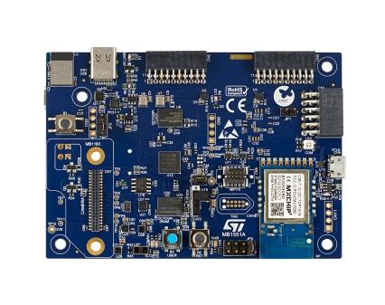
개요
B_U585I_IOT02A Discovery kit는 Cortex-M33 기반 STM32U585AI MCU와 폭넓은 connectivity를 제공합니다.
- UFBGA169 STM32U585AII6Q: flash 2MB, RAM 786KB
- 512-Mbit octal-SPI flash, 64-Mbit octal-SPI PSRAM, 256-Kbit I2C EEPROM
- USB FS sink/source power, 2.5W
- MXCHIP 802.11 b/g/n Wi-Fi
- ST Bluetooth Low Energy
- Digital microphone 2개
- Humidity·temperature sensor
- 3-axis magnetometer
- 3D accelerometer·gyroscope
- 260~1260hPa barometer
- Time-of-flight·gesture sensor
- Ambient-light sensor
- User/reset button 2개와 user LED 2개
- ST-LINK/V3, USB VBUS, external source 전원
STM32U585 hardware
STM32U5 family는 최대 160MHz Cortex-M33 32-bit RISC core를 사용하는 ultra-low-power MCU입니다.
- Standby 300nA, run 19.5µA/MHz FlexPowerControl
- TrustZone과 FPU가 있는 Cortex-M33
- 1.5DMIPS/MHz, 651 CoreMark(4.07 CoreMark/MHz)
- Securable I/O·memory·peripheral, RDP와 password debug, unique boot·HDP root of trust
- Embedded Root Secure Services 기반 Secure Firmware Installation, HUK secure storage, TF-M Secure Firmware Update
- DPA-resistant AES 2개·public-key accelerator, Octo-SPI on-the-fly decryption, HASH, active tamper, SP800-90B TRNG, 96-bit ID, user OTP 512byte
- 4~50MHz crystal, RTC 32kHz LSE, 16MHz RC, 32kHz low-power RC, 100kHz~48MHz multispeed oscillator 2개, PLL 3개, clock recovery 48MHz
- LDO와 on-the-fly voltage scaling SMPS
- Calendar·calibration RTC, fast I/O 최대 136개, capacitive channel 최대 24개
- Timer 최대 17개와 watchdog 2개: motor-control 2개, 32-bit 2개, 16-bit 5개, low-power 4개, SysTick 2개
- ART: instruction cache 8KB, external data cache 4KB
- ECC flash 2MB, ECC 설정에 따른 SRAM 786KB/722KB, external SRAM/PSRAM/NOR/NAND/FRAM, Octo-SPI 2개
- 14-bit·12-bit 2.5MSPS ADC, 12-bit DAC, PGA op-amp 2개, comparator 2개
- USB Type-C/PD와 OTG FS, SAI 2개, I2C 4개, USART 6개, SPI 3개(dual OCTOSPI SPI mode 포함 5개), FDCAN, SDMMC 2개
- Stop mode DMA 16/4-channel, multi-function digital filter와 sound-activity audio filter
- CRC, SWD, JTAG, Embedded Trace Macrocell, RNG
- Chrom-ART DMA2D와 digital camera interface
- CORDIC와 FMAC mathematical accelerator
Zephyr 지원 기능
| Interface | Controller | Driver/Component |
|---|---|---|
| NVIC | on-chip | nested vector interrupt controller |
| UART | on-chip | serial port-polling; serial port-interrupt |
| PINMUX | on-chip | pinmux |
| GPIO | on-chip | gpio |
| RNG | on-chip | True Random number generator |
| I2C | on-chip | i2c |
| SPI | on-chip | spi |
| DAC | on-chip | dac |
| ADC | on-chip | adc |
| WATCHDOG | on-chip | independent watchdog |
| USB | on-chip | usb_device |
| BKP SRAM | on-chip | Backup SRAM |
| PWM | on-chip | pwm |
| die-temp | on-chip | die temperature sensor |
| AES | on-chip | crypto |
| RADIO | STM32WB5MMG | Bluetooth Low Energy (BLE) |
| RTC | on-chip | rtc |
기본 설정은 boards/st/b_u585i_iot02a/b_u585i_iot02a_defconfig입니다.
Zephyr board option
Cortex-M33 SoC이므로 Secure·Non-Secure firmware를 모두 build할 수 있습니다.
| BOARD | Description |
|---|---|
| b_u585i_iot02a | TrustZone Disabled firmware |
| b_u585i_iot02a/stm32u585xx/ns | Non-Secure firmware |
TF-M Non-Secure build
west build -b b_u585i_iot02a/stm32u585xx/ns samples/tfm_integration/tfm_ipc/Flash 전에 생성된 regression script로 platform option byte를 설정하고 platform을 erase해야 하며 이 과정에서 TZEN도 설정됩니다.
./build/tfm/api_ns/regression.sh
west flash
TF-M sample 실행 후 일반 non-TFM binary로 돌아가려면 같은 script를 한 번 더 실행해 secure option을 정리해야 합니다. 그래도 TZEN은 설정된 채 남으므로 완전 해제가 필요하면 STM32CubeProgrammer를 사용합니다.
Connection과 I/O
GPIO controller는 A~I 9개입니다.
UART_1 TX/RX : PA9/PA10(ST-Link Virtual COM)LD1 : PH7LD2 : PH6user button : PC13SPI1 NSS/SCK/MISO/MOSI : PE12/P13/P14/P15I2C_1 SDA/SDL : PB9/PB8I2C_2 SDA/SDL : PH5/PH4DAC1 CH1 : PA4ADC1_IN15 : PB0USB OTG : PA11/PA12PWM4 : CN14 PB6PWM3 : CN4 PE4
기본 system clock은 16MHz HSI가 구동하는 PLL의 80MHz입니다. U(S)ART 4개 중 console은 UART1, 115200 8N1입니다. Backup SRAM 시험에서 VBAT를 VDD와 분리하려면 board 뒷면 SB6 jumper를 제거합니다.
Programming and debugging
Board에는 ST-LINK/V3가 내장됩니다. 기본 west flashing runner는 STM32CubeProgrammer이므로 설치가 필요합니다. -r openocd처럼 runner를 지정하면 Zephyr SDK OpenOCD, J-Link, pyOCD도 사용할 수 있습니다.
minicom -D /dev/ttyACM0west build -b b_u585i_iot02a samples/hello_world
west flashHello World! armDebugging
기본 debug flasher는 OpenOCD입니다.
west build -b b_u585i_iot02a samples/basic/blinky
west debug
TrustZone 완전 비활성화
TrustZone을 켜는 sample을 flash한 뒤 non-TrustZone sample을 실행하려면 TZEN과 RDP를 동시에 바꿔야 합니다. TZEN은 1→0, RDP는 DC→AA로 바뀝니다. RDP가 아직 DC가 아닐 수 있으므로 먼저 DC로 설정하고, mass erase가 실패하지 않도록 Write Protection 1·2 byte도 정리합니다.
1단계
U23 BOOT0 switch를 1로 둡니다. "BOOT0" silkscreen을 왼쪽에서 오른쪽으로 읽을 때 switch는 왼쪽입니다. 변경 후 B2 RST를 눌러 적용합니다.
2단계
STM32_Programmer_CLI -c port=/dev/ttyACM0 -ob rdp=0xDC3단계
STM32_Programmer_CLI -c port=/dev/ttyACM0 -tzenreg4단계
STM32_Programmer_CLI -c port=/dev/ttyACM0 -ob wrp1a_pstrt=0x7f
STM32_Programmer_CLI -c port=/dev/ttyACM0 -ob wrp1a_pend=0x0
STM32_Programmer_CLI -c port=/dev/ttyACM0 -ob wrp1b_pstrt=0x7f
STM32_Programmer_CLI -c port=/dev/ttyACM0 -ob wrp1b_pend=0x0
STM32_Programmer_CLI -c port=/dev/ttyACM0 -ob wrp2a_pstrt=0x7f
STM32_Programmer_CLI -c port=/dev/ttyACM0 -ob wrp2a_pend=0x0
STM32_Programmer_CLI -c port=/dev/ttyACM0 -ob wrp2b_pstrt=0x7f
STM32_Programmer_CLI -c port=/dev/ttyACM0 -ob wrp2b_pend=0x0
참고 자료
Source
출처
영어 원문에는 문단, 문서 지시문, 표, 코드, 코드 심벌, 경로를 그대로 보존했습니다.