Part 1
요약·해설
Digital power hardware, 6개 Zephyr controller와 joystick·LED·UCPD pin, ST-LINK/V3E workflow를 보존합니다.
STM32G474RET6
Cortex-M4
PD 3.0
STLINK-V3E
Part 2
접을 수 있는 영어 원문 전체
영어 원문 전체 펼치기
7F1EBC7A5AF0093EB801EEFF33B8D426EA0F28E9EEFE2C3C62CDCAB52C8DE7D8
.. _b_g474e_dpow1_board:

ST B-G474E-DPOW1 Discovery
##########################

Overview
********
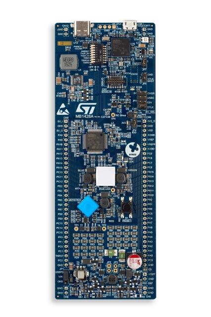
The B-G474E-DPOW1 Discovery kit is a digital power solution and a complete
demonstration and development platform for the STMicroelectronics STM32G474RET6
microcontroller. Leveraging the new HRTimer-oriented features, 96 Kbytes of
embedded RAM, math accelerator functions and USB-PD 3.0 offered by STM32G474RET6,
the B-G474E-DPOW1 Discovery kit, based on the USB 2.0 FS Type-C™ connector
interface, helps the user to prototype applications with digital power such as a
buck-boost converter, RGB power LED lighting or a class-D audio amplifier. The
B-G474E-DPOW1 Discovery kit does not require any separate probe, as it integrates
the STLINK-V3E debugger and programmer.

- STM32G474RET6 Arm® Cortex®-M4 core-based microcontroller, featuring 512 Kbytes
  of Flash memory and 128 Kbytes of SRAM, in LQFP64 package
- USB Type-C™ with USB 2.0 FS interface compatible with USB-PD 3.0
- RGB power LED for a bright lighting
- Digital power buck-boost converter with internal or external Input voltage and
  with onboard resistor loads
- Audio Class-D amplifier capable
- 4 user LEDs
- 3 LEDs for power and ST-LINK communication
- 4-direction joystick with a selection button
- Reset push-button
- Board connectors:
    - USB Type-C™
    - USB Micro-B
    - 2 x 32-pin header, 2.54 mm pitch, daughterboard extension connector for breadboard connection
- Flexible power-supply options: ST-LINK USB VBUS or USB Type-C™ VBUS or external source
- On-board STLINK-V3E debugger/programmer with USB re-enumeration capability: mass storage,
  Virtual COM port, and debug port

.. image:: ../../../../../../../boards/st/b_g474e_dpow1/doc/img/b_g474e_dpow1.jpg
   :align: center
   :alt: B-G474E-DPOW1

More information about the board can be found at the `B-G474E-DPOW1 website`_.


More information about STM32G474RE can be found here:

- `G474RE on www.st.com`_
- `STM32G4 reference manual`_


Supported Features
==================

The Zephyr b_g474e_dpow1 board configuration supports the following hardware features:

+-----------+------------+-------------------------------------+
| Interface | Controller | Driver/Component                    |
+===========+============+=====================================+
| NVIC      | on-chip    | nested vector interrupt controller  |
+-----------+------------+-------------------------------------+
| UART      | on-chip    | serial port-polling;                |
|           |            | serial port-interrupt               |
+-----------+------------+-------------------------------------+
| GPIO      | on-chip    | gpio                                |
+-----------+------------+-------------------------------------+
| USB       | on-chip    | usb                                 |
+-----------+------------+-------------------------------------+
| UCPD      | on-chip    | ucpd                                |
+-----------+------------+-------------------------------------+
| WATCHDOG  | on-chip    | independent watchdog                |
+-----------+------------+-------------------------------------+

Other hardware features are not yet supported in this Zephyr port.

The default configuration can be found in the defconfig file:
:zephyr_file:`boards/st/b_g474e_dpow1/b_g474e_dpow1_defconfig`

Connections and IOs
===================

Each of the GPIO pins can be configured by software as output (push-pull or open-drain), as
input (with or without pull-up or pull-down), or as peripheral alternate function. Most of the
GPIO pins are shared with digital or analog alternate functions. All GPIOs are high current
capable except for analog inputs.

Default Zephyr Peripheral Mapping:
----------------------------------

- UART_3 TX/RX       : PC10/PC11 (ST-Link Virtual Port Com)
- BUTTON (JOY_SEL)   : PC13
- BUTTON (JOY_LEFT)  : PC4
- BUTTON (JOY_DOWN)  : PC5
- BUTTON (JOY_RIGHT) : PB2
- BUTTON (JOY_UP)    : PB10
- LED (DOWN BLUE)    : PA15
- LED (LEFT ORANGE)  : PB1
- LED (UP RED)       : PB5
- LED (RIGHT GREEN)  : PB7
- USB DM             : PA11
- USB DP             : PA12
- UCPD CC2           : PB4
- UCPD CC1           : PB6

For more details please refer to `B-G474E-DPOW1 Discovery board User Manual`_.

Programming and Debugging
*************************

Applications for the ``b_g474e_dpow1`` board configuration can be built and
flashed in the usual way (see :ref:`build_an_application` and
:ref:`application_run` for more details).

Flashing
========

The B-G474E-DPOW1 Discovery board includes an ST-LINK/V3E embedded debug tool interface.

.. code-block:: console

   $ west flash

Flashing an application to the B_G474E_DPOW1
--------------------------------------------

Here is an example for the :zephyr:code-sample:`blinky` application.

.. zephyr-app-commands::
   :zephyr-app: samples/basic/blinky
   :board: b_g474e_dpow1
   :goals: build flash

You will see the LED blinking every second.

Debugging
=========

You can debug an application in the usual way. Here is an example for the
:ref:`hello_world` application.

.. zephyr-app-commands::
   :zephyr-app: samples/hello_world
   :board: b_g474e_dpow1
   :maybe-skip-config:
   :goals: debug

References
**********

.. target-notes::

.. _B-G474E-DPOW1 website:
   https://www.st.com/en/evaluation-tools/b-g474e-dpow1.html

.. _STM32G4 reference manual:
   https://www.st.com/resource/en/reference_manual/rm0440-stm32g4-series-advanced-armbased-32bit-mcus-stmicroelectronics.pdf

.. _B-G474E-DPOW1 Discovery board User Manual:
   https://www.st.com/resource/en/user_manual/um2577-discovery-kit-with-stm32g474re-mcu-stmicroelectronics.pdf

.. _G474RE on www.st.com:
   https://www.st.com/en/microcontrollers-microprocessors/stm32g474re.html
Part 3
한국어 전문 번역
개요
B-G474E-DPOW1 Discovery kit는 STM32G474RET6 microcontroller용 digital power solution이자 완전한 demonstration·development platform입니다. HRTimer 중심 기능, 수학 accelerator, USB-PD 3.0과 USB 2.0 FS Type-C interface를 활용해 buck-boost converter, RGB power LED 조명, class-D audio amplifier 같은 digital power application을 prototype할 수 있습니다. STLINK-V3E debugger/programmer가 내장되어 별도 probe가 필요하지 않습니다.
Board hardware
- LQFP64 STM32G474RET6 Arm Cortex-M4 MCU: flash 512Kbytes, SRAM 128Kbytes
- USB-PD 3.0 호환 USB 2.0 FS Type-C
- 고휘도 RGB power LED
- Internal/external input voltage와 onboard resistor load를 갖춘 digital power buck-boost converter
- Audio class-D amplifier 기능
- User LED 4개
- Power·ST-LINK communication LED 3개
- Selection button이 있는 4-direction joystick
- Reset push-button
- USB Type-C, USB Micro-B connector
- Breadboard daughterboard용 2×32-pin 2.54mm header
- ST-LINK USB VBUS, USB Type-C VBUS, external source의 유연한 전원
- Mass-storage, Virtual COM, debug port로 USB re-enumeration하는 onboard STLINK-V3E
상세 정보는 B-G474E-DPOW1, STM32G474RE, STM32G4 reference manual을 참고합니다.
Zephyr 지원 기능
| Interface | Controller | Driver/Component |
|---|---|---|
| NVIC | on-chip | nested vector interrupt controller |
| UART | on-chip | serial port-polling; serial port-interrupt |
| GPIO | on-chip | gpio |
| USB | on-chip | usb |
| UCPD | on-chip | ucpd |
| WATCHDOG | on-chip | independent watchdog |
그 밖의 hardware 기능은 이 Zephyr port에서 아직 지원하지 않습니다. 기본 설정은 boards/st/b_g474e_dpow1/b_g474e_dpow1_defconfig입니다.
Connection과 I/O
GPIO는 push-pull/open-drain output, pull-up/down 유무를 포함한 input, peripheral alternate function으로 software 설정할 수 있습니다. 대부분 digital·analog alternate function과 공유되고 analog input을 제외한 GPIO는 high-current capable입니다.
기본 Zephyr mapping
UART_3 TX/RX : PC10/PC11(ST-Link Virtual COM)JOY_SEL : PC13JOY_LEFT : PC4JOY_DOWN : PC5JOY_RIGHT : PB2JOY_UP : PB10DOWN BLUE LED : PA15LEFT ORANGE LED : PB1UP RED LED : PB5RIGHT GREEN LED : PB7USB DM : PA11USB DP : PA12UCPD CC2 : PB4UCPD CC1 : PB6
Programming and debugging
b_g474e_dpow1 application은 일반 Zephyr 방식으로 build하고 flash합니다. Board에는 ST-LINK/V3E debug interface가 내장되어 있습니다.
west flashBlinky build와 flash
west build -b b_g474e_dpow1 samples/basic/blinky
west flash
LED가 1초마다 깜박입니다.
Debugging
west build -b b_g474e_dpow1 samples/hello_world
west debug
참고 자료
Source
출처
영어 원문에는 문단, 문서 지시문, 표, 코드, 코드 심벌, 경로를 그대로 보존했습니다.