Part 1
요약·해설
MicroMod 공통 interface와 nRF52840 target을 구분하고 carrier별 flashing, LED·128Mb QSPI test까지 설명합니다.
micromod/nrf52840
Cortex-M4F
2.4GHz
128Mb
Part 2
접을 수 있는 영어 원문 전체
영어 원문 전체 펼치기
DF226A8A682D5DBA81222E7CDA0B1AB87B9321C71F7A530F56CE41736BC04938
.. _boardname_linkname:

SparkFun MicroMod board Processor
#################################

Overview
********

MicroMod is a solderless, modular interface ecosystem that uses the M.2 standard
to mix and match your choice of processor with specific Function Boards or
stand-alone Carrier Boards. A MicroMod processor board is approximately 22x22 mm,
and can insert into any MicroMod carrier board. More information can be found in
the `Micromod specification website`_.

All Micromod board targets support the following hardware features:

- USB host mode compliant to 2.0 specification
- GPIO
- 2 UART
- 2 I2C
- 2 SPI
- 2 ADC
- 2 PWM
- Watchdog Timer (WDT)

.. figure:: ../../../../../../../boards/sparkfun/micromod/doc/img/sparkfun_micromod.webp
   :align: center
   :alt: Sparkfun Micromod board

   Sparkfun Micromod board (Credit: https://www.sparkfun.com)

Zephyr currently supports the following SoCs:

- ``micromod/nrf52840``

SparkFun MicroMod nRF52840 board Processor
##########################################

Overview
********

The ``micromod/nrf52840`` board target features the nRF52840 SoC
from Nordic Semiconductor, the SparkFun MicroMod nRF52840 Processor offers
a powerful combination of ARM Cortex-M4 CPU and 2.4 GHz Bluetooth transceiver
in the MicroMod form-factor. More information can be found in
the `Micromod nRF52840 guide`_.

Hardware
********

The ``micromod/nrf52840`` board target supports the following
hardware features:

- ARM Cortex-M4 CPU with floating point unit (FPU)

   - 1MB internal Flash
   - 256kB internal RAM

- Integrated 2.4GHz radio with support for Bluetooth Low Energy (BLE) and ieee802154
- USB 2.0 full speed (12 Mbps) controller
- QSPI with 128Mb flash memory
- ARM TrustZone Cryptocell 310 security subsystem
- USB host mode compliant to 2.0 specification
- GPIO
- 2 UART
- 2 I2C
- 2 SPI
- 2 ADC
- 2 PWM
- Watchdog Timer (WDT)

Supported Features
==================

The Zephyr ``micromod/nrf52840`` board target supports the following hardware
features:

+-----------+------------+-------------------------------------+
| Interface | Controller | Driver/Component                    |
+===========+============+=====================================+
| NVIC      | on-chip    | nested vector interrupt controller  |
+-----------+------------+-------------------------------------+
| SYSTICK   | on-chip    | system clock                        |
+-----------+------------+-------------------------------------+
| RADIO     | on-chip    | Bluetooth,                          |
|           |            | ieee802154                          |
+-----------+------------+-------------------------------------+
| UART      | on-chip    | serial port                         |
+-----------+------------+-------------------------------------+
| GPIO      | on-chip    | gpio                                |
+-----------+------------+-------------------------------------+
| PINMUX    | on-chip    | pinmux                              |
+-----------+------------+-------------------------------------+
| FLASH     | on-chip    | flash                               |
+-----------+------------+-------------------------------------+
| SPI       | on-chip    | spi                                 |
+-----------+------------+-------------------------------------+
| I2C       | on-chip    | i2c                                 |
+-----------+------------+-------------------------------------+
| USB       | on-chip    | usb                                 |
+-----------+------------+-------------------------------------+
| QSPI      | on-chip    | nordic,nrf-qspi                     |
+-----------+------------+-------------------------------------+


Connections and IOs
===================

LED
---

* Led0 (blue) = P0.13

Micromod header
---------------

* micromod_1_uart = uart0
* micromod_2_uart = uart1
* micromod_0_i2c = i2c0
* micromod_1_i2c = i2c1
* micromod_0_spi = spi2
* micromod_header compatible with ``sparkfun,micromod-gpio``

Programming and Debugging
*************************

Applications for the ``micromod/nrf52840`` board target can be
built, flashed, and debugged in the usual way. See
:ref:`build_an_application` and :ref:`application_run` for more details on
building and running.

Flashing
========

Follow the instructions in the :ref:`nordic_segger` page to install
and configure all the necessary software. Further information can be
found in :ref:`nordic_segger_flashing`. Then build and flash
applications as usual (see :ref:`build_an_application` and
:ref:`application_run` for more details).

The flashing tool will depend on the carrier used along with the board.
In the case of `Sparkfun asset tracking carrier`, it is possible to use
the SWD interface along with a J-Link.

Here is an example for the :ref:`hello_world` application.

First, run your favorite terminal program to listen for output.

.. code-block:: console

   $ minicom -D <tty_device> -b 115200

Replace :code:`<tty_device>` with the port where the board nRF52840 DK
can be found. For example, under Linux, :code:`/dev/ttyACM0`.

Then build and flash the application in the usual way.

.. zephyr-app-commands::
   :zephyr-app: samples/hello_world
   :board: micromod/nrf52840
   :goals: build flash

Debugging
=========

Refer to the :ref:`nordic_segger` page to learn about debugging Nordic boards with a
Segger IC.

In case of using a Nordic Segger Jlink, it is possible to configure the app to use Segger Real
Time Transfer (RTT) for debugging. In this case, build your app with the
:ref:`RTT snippet <snippet-rtt-console>`.

Testing the on-board LED
************************

There is a sample that allow you to test the LED on the board is working properly
with Zephyr:

* :zephyr:code-sample:`blinky`

You can build and flash the example to make sure Zephyr is running correctly on
your board. The button and LED definitions can be found in
:zephyr_file:`boards/sparkfun/micromod/micromod_nrf52840.dts`.

Testing the 128Mb qspi memory flash
***********************************

The ``micromod/nrf52840`` board target has a built-in NOR flash memory connected
to the qspi interface. It can be tested with the samples/drivers/jesd216 app.

.. zephyr-app-commands::
   :zephyr-app: samples/drivers/jesd216
   :board: micromod/nrf52840
   :goals: build flash

References
**********

.. target-notes::

.. _Micromod specification website: https://www.sparkfun.com/micromod
.. _Micromod nRF52840 guide: https://learn.sparkfun.com/tutorials/micromod-nrf52840-processor-hookup-guide
.. _J-Link Software and documentation pack: https://www.segger.com/jlink-software.html
.. _nRF52840 Product Specification: http://infocenter.nordicsemi.com/pdf/nRF52840_PS_v1.0.pdf
Part 3
한국어 전문 번역
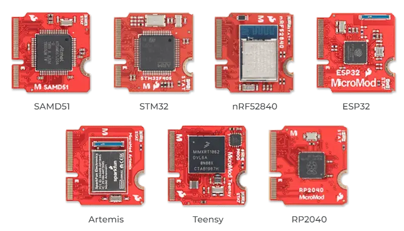
MicroMod ecosystem 개요
MicroMod는 M.2 표준을 이용해 원하는 processor를 특정 Function Board 또는 standalone Carrier Board와 조합하는 solderless modular interface ecosystem입니다. Processor board 크기는 약 22×22mm이며 어떤 MicroMod carrier board에도 삽입할 수 있습니다. 자세한 내용은 MicroMod specification에서 확인합니다.
모든 MicroMod board target은 다음 hardware 기능을 지원합니다.
- USB 2.0 specification 준수 host mode
- GPIO
- UART 2개
- I2C 2개
- SPI 2개
- ADC 2개
- PWM 2개
- Watchdog Timer(WDT)
Zephyr 3.7.0에서 현재 지원하는 SoC target은 micromod/nrf52840입니다.
MicroMod nRF52840 Processor
개요
micromod/nrf52840 target은 Nordic Semiconductor nRF52840 SoC를 사용합니다. Arm Cortex-M4 CPU와 2.4GHz Bluetooth transceiver를 MicroMod form factor에 결합하며 상세 연결 방법은 MicroMod nRF52840 guide를 참고합니다.
Hardware
- FPU가 있는 Arm Cortex-M4 CPU
- Internal flash 1MB
- Internal RAM 256kB
- BLE와 ieee802154를 지원하는 integrated 2.4GHz radio
- USB 2.0 full-speed(12Mbps) controller
- 128Mb flash memory가 연결된 QSPI
- Arm TrustZone CryptoCell 310 security subsystem
- USB 2.0 host mode
- GPIO
- UART 2개
- I2C 2개
- SPI 2개
- ADC 2개
- PWM 2개
- Watchdog Timer(WDT)
Zephyr 지원 기능
| Interface | Controller | Driver/Component |
|---|---|---|
| NVIC | on-chip | nested vector interrupt controller |
| SYSTICK | on-chip | system clock |
| RADIO | on-chip | Bluetooth, ieee802154 |
| UART | on-chip | serial port |
| GPIO | on-chip | gpio |
| PINMUX | on-chip | pinmux |
| FLASH | on-chip | flash |
| SPI | on-chip | spi |
| I2C | on-chip | i2c |
| USB | on-chip | usb |
| QSPI | on-chip | nordic,nrf-qspi |
Connection과 I/O
Blue LED0는 P0.13에 연결됩니다. MicroMod header mapping은 다음과 같습니다.
micromod_1_uart = uart0micromod_2_uart = uart1micromod_0_i2c = i2c0micromod_1_i2c = i2c1micromod_0_spi = spi2micromod_headercompatible은sparkfun,micromod-gpio
Programming and debugging
micromod/nrf52840 application은 일반적인 Zephyr 방식으로 build, flash, debug할 수 있습니다.
Flashing
Nordic Segger 지침에 따라 필요한 software를 설치·설정합니다. 실제 flashing tool은 processor board와 결합한 carrier에 따라 달라집니다. SparkFun asset tracking carrier에서는 SWD interface와 J-Link를 사용할 수 있습니다.
먼저 terminal을 열어 115200 baud output을 기다립니다.
minicom -D <tty_device> -b 115200<tty_device>는 board가 연결된 port이며 Linux에서는 예를 들어 /dev/ttyACM0입니다. 그런 다음 hello_world를 build하고 flash합니다.
west build -b micromod/nrf52840 samples/hello_world
west flash
Debugging
Nordic board의 Segger IC debugging 절차를 사용합니다. Nordic Segger J-Link에서는 Segger Real Time Transfer(RTT)를 쓰도록 application을 구성할 수 있으며 이때 RTT console snippet을 포함해 build합니다.
Board test
Onboard LED
blinky sample로 LED 동작과 Zephyr 실행을 확인합니다. Button과 LED 정의는 boards/sparkfun/micromod/micromod_nrf52840.dts에 있습니다.
128Mb QSPI NOR flash
QSPI에 연결된 builtin NOR flash는 samples/drivers/jesd216 application으로 시험합니다.
west build -b micromod/nrf52840 samples/drivers/jesd216
west flash
참고 자료
Source
출처
영어 원문에는 문단, 문서 지시문, 표, 코드, 코드 심벌, 경로를 그대로 보존했습니다.