Part 1
요약·해설
지원 interface 11개와 I/O 16개, TB004 drag-and-drop flash 절차를 정리합니다.
EFR32MG12
Cortex-M4F
38.4MHz
J-Link
Part 2
접을 수 있는 영어 원문 전체
영어 원문 전체 펼치기
F012D16990F48AAD8AA8369B27200EE4A0CB74F2E4218CFA8ADF5838435B16E8
.. _sltb004a:

EFR32MG12 Thunderboard (SLTB004A)
#################################

Overview
********

The EFR32MG12 Thunderboard (a.k.a Thunderboard Sense 2) contains an MCU
from the EFR32MG12 family built on ARM® Cortex®-M4F processor with low
power capabilities.

.. image:: ../../../../../../../../boards/silabs/dev_kits/sltb004a/doc/sltb004a.jpg
   :align: center
   :alt: EFR32MG12 SLTB004A

Hardware
********

- EFR32MG12 Mighty Gecko Wireless SoC with 38.4 MHz operating frequency
- ARM® Cortex® M4 core with 256 kB RAM and 1024 kB Flash
- Macronix ultra low power 8-Mbit SPI flash (MX25R8035F)
- 2.4 GHz ceramic antenna for wireless transmission
- Silicon Labs Si7021 relative humidity and temperature sensor
- Silicon Labs Si1133 UV index and ambient light sensor
- Silicon Labs Si7210 hall effect sensor
- Bosch Sensortec BMP280 barometric pressure sensor
- ams CCS811 indoor air quality gas sensor
- TDK InvenSense ICM-20648 6-axis inertial sensor
- TDK InvenSense ICS-43434 MEMS microphone
- Four high brightness RGB LEDs from Broadcom Limited (ASMT-YTB7-0AA02)
- One bi-color LED and two push buttons
- Power enable signals for fine grained power-control
- On-board SEGGER J-Link debugger for easy programming and debugging, which
  includes a USB virtual COM port
- Mini Simplicity connector for access to energy profiling and advanced wireless
  network debugging
- Breakout pads for GPIO access and connection to external hardware
- Reset button
- Automatic switch-over between USB and battery power
- CR2032 coin cell holder and external battery connector

For more information about the EFR32MG12 SoC and Thunderboard Sense 2 board:

- `EFR32MG12 Datasheet`_
- `EFR32MG12 Reference Manual`_
- `SLTB004A User Guide`_
- `SLTB004A Schematics`_

Supported Features
==================

The sltb004a board configuration supports the following hardware features:

+-----------+------------+-------------------------------------+
| Interface | Controller | Driver/Component                    |
+===========+============+=====================================+
| MPU       | on-chip    | memory protection unit              |
+-----------+------------+-------------------------------------+
| NVIC      | on-chip    | nested vector interrupt controller  |
+-----------+------------+-------------------------------------+
| SYSTICK   | on-chip    | systick                             |
+-----------+------------+-------------------------------------+
| COUNTER   | on-chip    | rtcc                                |
+-----------+------------+-------------------------------------+
| FLASH     | on-chip    | flash memory                        |
+-----------+------------+-------------------------------------+
| GPIO      | on-chip    | gpio                                |
+-----------+------------+-------------------------------------+
| UART      | on-chip    | serial port-polling;                |
|           |            | serial port-interrupt               |
+-----------+------------+-------------------------------------+
| I2C       | on-chip    | i2c port-polling                    |
+-----------+------------+-------------------------------------+
| SPI(M)    | on-chip    | spi port-polling                    |
+-----------+------------+-------------------------------------+
| WATCHDOG  | on-chip    | watchdog                            |
+-----------+------------+-------------------------------------+
| TRNG      | on-chip    | true random number generator        |
+-----------+------------+-------------------------------------+

The default configuration can be found in
:zephyr_file:`boards/silabs/dev_kits/sltb004a/sltb004a_defconfig`

Other hardware features are currently not supported by the port.

Connections and IOs
===================

The EFR32MG12 SoC has eight gpio controllers (PORTA, PORTB, PORTC, PORTD,
PORTF, PORTI, PORTJ and PORTK).

In the following table, the column Name contains Pin names. For example, PE2
means Pin number 2 on PORTE and #27 represents the location bitfield , as used
in the board's and microcontroller's datasheets and manuals.

+------+-------------+-----------------------------------+
| Name | Function    | Usage                             |
+======+=============+===================================+
| PD8  | GPIO        | LED0 (RED)                        |
+------+-------------+-----------------------------------+
| PD9  | GPIO        | LED1 (GREEN)                      |
+------+-------------+-----------------------------------+
| PD14 | GPIO        | SW0 Push Button PB0               |
+------+-------------+-----------------------------------+
| PD15 | GPIO        | Push Button PB1                   |
+------+-------------+-----------------------------------+
| PA0  | UART_TX     | UART TX Console VCOM_TX US0_TX #0 |
+------+-------------+-----------------------------------+
| PA1  | UART_RX     | UART RX Console VCOM_RX US0_RX #0 |
+------+-------------+-----------------------------------+
| PF3  | UART_TX     | EXP12_UART_TX LEU0_TX #27         |
+------+-------------+-----------------------------------+
| PF4  | UART_RX     | EXP14_UART_RX LEU0_RX #27         |
+------+-------------+-----------------------------------+
| PC10 | I2C_SDA     | EXP16_I2C_SDA I2C0_SDA #15        |
+------+-------------+-----------------------------------+
| PC11 | I2C_SCL     | EXP15_I2C_SCL I2C0_SCL #15        |
+------+-------------+-----------------------------------+
| PB6  | I2C_SDA     | CCS811_I2C_SDA I2C1_SDA #6        |
+------+-------------+-----------------------------------+
| PB7  | I2C_SCL     | CCS811_I2C_SCL I2C1_SCL #6        |
+------+-------------+-----------------------------------+
| PK0  | SPI_MOSI    | Flash MOSI US2_TX #29             |
+------+-------------+-----------------------------------+
| PK2  | SPI_MISO    | Flash MISO US2_RX #30             |
+------+-------------+-----------------------------------+
| PF7  | SPI_SCLK    | Flash SCLK US2_CLK #18            |
+------+-------------+-----------------------------------+
| PK1  | SPI_CS      | Flash Chip Select (GPIO)          |
+------+-------------+-----------------------------------+

System Clock
============

The EFR32MG12 SoC is configured to use the 38.4 MHz external oscillator on the
board.

Serial Port
===========

The EFR32MG12 SoC has four USARTs and one Low Energy UARTs (LEUART with 9600
maximum baudrate). USART0 is configured as the Zephyr console and is connected
to the On-Board J-Link Debugger that presents a virtual COM port for general
purpose application serial data transfer with this interface.

Programming and Debugging
*************************

.. note::
   Before using the kit the first time, you should update the J-Link firmware
   from `J-Link-Downloads`_

Flashing
========

The SLTB004A includes an `J-Link`_ serial and debug adaptor built into the
board. The adaptor provides:

- A USB connection to the host computer, which exposes a Mass Storage and a
  USB Serial Port.
- A Serial Flash device, which implements the USB flash disk file storage.
- A physical UART connection which is relayed over interface USB Serial port.

Flashing an application to SLTB004A
-----------------------------------

The sample application :ref:`hello_world` is used for this example.
Build the Zephyr kernel and application:

.. zephyr-app-commands::
   :zephyr-app: samples/hello_world
   :board: sltb004a
   :goals: build

Connect the SLTB004A to your host computer using the USB port and you
should see a USB connection which exposes a Mass Storage (TB004) and a
USB Serial Port. Copy the generated zephyr.bin in the SLTB004A drive.

Open a serial terminal (minicom, putty, etc.) with the following settings:

- Speed: 115200
- Data: 8 bits
- Parity: None
- Stop bits: 1

Reset the board and you should be able to see on the corresponding Serial Port
the following message:

.. code-block:: console

   Hello World! sltb004a


.. _SLTB004A User Guide:
   https://www.silabs.com/documents/public/user-guides/ug309-sltb004a-user-guide.pdf

.. _SLTB004A Schematics:
   https://www.silabs.com/documents/public/schematic-files/BRD4166A-D00-schematic.pdf

.. _EFR32MG12 Datasheet:
   https://www.silabs.com/documents/public/data-sheets/efr32mg12-datasheet.pdf

.. _EFR32MG12 Reference Manual:
   https://www.silabs.com/documents/public/reference-manuals/efr32xg12-rm.pdf

.. _J-Link:
   https://www.segger.com/jlink-debug-probes.html

.. _J-Link-Downloads:
   https://www.segger.com/downloads/jlink
Part 3
한국어 전문 번역
개요
EFR32MG12 Thunderboard(SLTB004A, Thunderboard Sense 2)는 low-power ARM Cortex-M4F 기반 EFR32MG12 MCU board입니다.
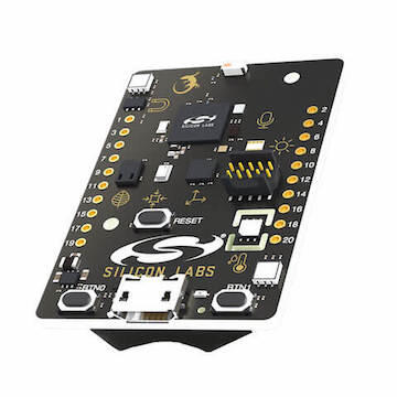
하드웨어
- EFR32MG12 Mighty Gecko, 38.4MHz
- Cortex-M4, RAM 256kB, Flash 1024kB
- MX25R8035F 8-Mbit SPI flash와 2.4GHz ceramic antenna
- Si7021 humidity/temperature, Si1133 UV/ambient light, Si7210 Hall, BMP280 pressure, CCS811 air-quality sensor
- ICM-20648 6-axis sensor, ICS-43434 MEMS microphone
- Broadcom RGB LED 4개, bi-color LED 1개, push button 2개
- Fine-grained power enable, onboard J-Link/VCOM, Mini Simplicity, GPIO breakout, reset
- USB/battery automatic switch-over, CR2032 holder와 external battery connector
지원 기능
| Interface | Controller | Driver/Component |
|---|---|---|
| MPU | on-chip | memory protection unit |
| NVIC | on-chip | nested vector interrupt controller |
| SYSTICK | on-chip | systick |
| COUNTER | on-chip | rtcc |
| FLASH | on-chip | flash memory |
| GPIO | on-chip | gpio |
| UART | on-chip | serial port-polling; serial port-interrupt |
| I2C | on-chip | i2c port-polling |
| SPI(M) | on-chip | spi port-polling |
| WATCHDOG | on-chip | watchdog |
| TRNG | on-chip | true random number generator |
기본 설정은 sltb004a_defconfig에 있고 그 밖의 hardware는 현재 port에서 지원하지 않습니다.
Connection과 I/O
EFR32MG12에는 PORTA/B/C/D/F/I/J/K의 GPIO controller 8개가 있습니다. #27 같은 값은 datasheet의 location bitfield입니다.
| Name | Function | Usage |
|---|---|---|
| PD8 | GPIO | LED0 (RED) |
| PD9 | GPIO | LED1 (GREEN) |
| PD14 | GPIO | SW0 Push Button PB0 |
| PD15 | GPIO | Push Button PB1 |
| PA0 | UART_TX | UART TX Console VCOM_TX US0_TX #0 |
| PA1 | UART_RX | UART RX Console VCOM_RX US0_RX #0 |
| PF3 | UART_TX | EXP12_UART_TX LEU0_TX #27 |
| PF4 | UART_RX | EXP14_UART_RX LEU0_RX #27 |
| PC10 | I2C_SDA | EXP16_I2C_SDA I2C0_SDA #15 |
| PC11 | I2C_SCL | EXP15_I2C_SCL I2C0_SCL #15 |
| PB6 | I2C_SDA | CCS811_I2C_SDA I2C1_SDA #6 |
| PB7 | I2C_SCL | CCS811_I2C_SCL I2C1_SCL #6 |
| PK0 | SPI_MOSI | Flash MOSI US2_TX #29 |
| PK2 | SPI_MISO | Flash MISO US2_RX #30 |
| PF7 | SPI_SCLK | Flash SCLK US2_CLK #18 |
| PK1 | SPI_CS | Flash Chip Select (GPIO) |
System clock과 serial
Board의 38.4MHz external oscillator를 사용합니다. USART 4개와 최대 9600 baud LEUART 1개가 있으며 USART0가 J-Link virtual COM port를 통한 Zephyr console입니다.
Programming and debugging
Onboard J-Link는 host USB, mass storage·USB serial, serial flash와 physical UART relay를 제공합니다.
Flash
west build -b sltb004a samples/hello_worldUSB로 연결해 나타나는 TB004 mass-storage drive에 생성된 zephyr.bin을 복사합니다. Terminal은 115200 baud, 8 data bit, parity 없음, stop bit 1로 열고 reset합니다.
Hello World! sltb004a참고 자료
Source
출처
영어 원문에는 문단, 문서 지시문, 표, 코드, 코드 심벌, 경로를 그대로 보존했습니다.