Part 1
요약·해설
180 MHz K66, KSZ8794CNX와 RJ45, five pinmux/GPIO pairs, OpenSDA firmware 호환성, RTT-only console을 설명합니다.
MK66FN2M0 · 180 MHz
KSZ8794CNX · 4-port 10/100
J-Link-OB · OpenSDA
SEGGER RTT only
Part 2
접을 수 있는 영어 원문 전체
영어 원문 전체 펼치기
2C9A8A8C755938E080080F2360C5FCF7C9EAB6005A363B14461044F3F58D88BF
.. _ip_k66f:

SEGGER IP Switch Board
######################

Overview
********

The Segger IP Switch Board is a Evaluation board based on NXP Kinetis K66 MCU.
It comes with Micrel/Microchip KSZ8794CNX integrated 4-port 10/100 managed
Ethernet switch with Gigabit RGMII/MII/RMII interface.

- KSZ8794CNX enables evaluation for switch functions
- On-board debug probe J-Link-OB for programming

.. image:: ../../../../../../../boards/segger/ip_k66f/doc/ip_k66f.jpg
   :align: center
   :alt: IP-K66F

Hardware
********

- MK66FN2M0VMD18 MCU (180 MHz, 2 MB flash memory, 256 KB RAM, low-power,
  crystal-less USB
- Dual role USB interface with micro-B USB connector
- 2 User LED
- On-board debug probe J-Link-OB for programming
- Micrel/Microchip Ethernet Switch KSZ8794CNX with 3 RJ45 connectors

For more information about the K66F SoC and IP-K66F board:

- `K66F Website`_
- `K66F Datasheet`_
- `K66F Reference Manual`_
- `IP-K66F Website`_
- `IP-K66F User Guide`_
- `IP-K66F Schematics`_

Supported Features
==================

The ip_k66f board configuration supports the following hardware features:

+-----------+------------+-------------------------------------+
| Interface | Controller | Driver/Component                    |
+===========+============+=====================================+
| NVIC      | on-chip    | nested vector interrupt controller  |
+-----------+------------+-------------------------------------+
| SYSTICK   | on-chip    | systick                             |
+-----------+------------+-------------------------------------+
| PINMUX    | on-chip    | pinmux                              |
+-----------+------------+-------------------------------------+
| GPIO      | on-chip    | gpio                                |
+-----------+------------+-------------------------------------+
| WATCHDOG  | on-chip    | watchdog                            |
+-----------+------------+-------------------------------------+
| FLASH     | on-chip    | soc flash                           |
+-----------+------------+-------------------------------------+
| RTC       | on-chip    | rtc                                 |
+-----------+------------+-------------------------------------+

The default configuration can be found in
:zephyr_file:`boards/segger/ip_k66f/ip_k66f_defconfig`

Micrel/Microchip KSZ8794CNX Ethernet Switch is supported
(see :zephyr:code-sample:`dsa` sample).

Connections and IOs
===================

The K66F SoC has five pairs of pinmux/gpio controllers.

+-------+-----------------+---------------------------+
| Name  | Function        | Usage                     |
+=======+=================+===========================+
| PTA8  | GPIO            | Red LED                   |
+-------+-----------------+---------------------------+
| PTA10 | GPIO            | RED LED                   |
+-------+-----------------+---------------------------+

System Clock
============

The K66F SoC is configured to use the 12 MHz low gain crystal oscillator on the
board with the on-chip PLL to generate a 180 MHz system clock.

Serial Port
===========

The K66F SoC has six UARTs. None of them are used.

Programming and Debugging
*************************

Build and flash applications as usual (see :ref:`build_an_application` and
:ref:`application_run` for more details).

Configuring a Debug Probe
=========================

A debug probe is used for both flashing and debugging the board. This board is
configured by default to use the :ref:`opensda-jlink-onboard-debug-probe`.

:ref:`opensda-jlink-onboard-debug-probe`
--------------------------------------------------

Install the :ref:`jlink-debug-host-tools` and make sure they are in your search
path.

Follow the instructions in :ref:`opensda-jlink-onboard-debug-probe` to program
the `OpenSDA J-Link Generic Firmware for V3.2 Bootloader`_. Note that Segger
does provide an OpenSDA J-Link Board-Specific Firmware for this board, however
it is not compatible with the DAPLink bootloader.

The default flasher is ``jlink`` using the built-in SEGGER Jlink interface.

Flashing
========

Here is an example for the :zephyr:code-sample:`blinky` application.

.. zephyr-app-commands::
   :zephyr-app: samples/basic/blinky
   :board: ip_k66f
   :goals: flash

Red LED0 should blink at 1 second delay.

Debugging
=========

Here is an example for the :zephyr:code-sample:`blinky` application.

.. zephyr-app-commands::
   :zephyr-app: samples/basic/blinky
   :board: ip_k66f
   :goals: debug

Step through the application in your debugger.

.. _IP-K66F Website:
   https://www.segger.com/evaluate-our-software/segger/embosip-switch-board/

.. _IP-K66F User Guide:
   https://www.segger.com/downloads/emnet/UM06002

.. _IP-K66F Schematics:
   https://www.segger.com/downloads/emnet/embOSIP_SwitchBoard_V2.0_WEB_Schematic.pdf

.. _K66F Website:
   https://www.nxp.com/products/processors-and-microcontrollers/arm-microcontrollers/general-purpose-mcus/k-series-cortex-m4/k6x-ethernet/kinetis-k66-180-mhz-dual-high-speed-full-speed-usbs-2mb-flash-microcontrollers-mcus-based-on-arm-cortex-m4-core:K66_180

.. _K66F Datasheet:
   https://www.nxp.com/docs/en/data-sheet/K66P144M180SF5V2.pdf

.. _K66F Reference Manual:
   https://www.nxp.com/webapp/Download?colCode=K66P144M180SF5RMV2

.. _OpenSDA J-Link Generic Firmware for V3.2 Bootloader:
   https://www.segger.com/downloads/jlink/OpenSDA_V3_2

Serial console
==============

The ``ip_k66f`` board only uses Segger's RTT console for providing serial
console. There is no physical serial port available.

- To communicate with this board one needs in one console:

``/opt/SEGGER/JLink_V664/JLinkRTTLogger -Device MK66FN2M0XXX18 -RTTChannel 1 -if SWD -Speed 4000 ~/rtt.log``

- In another one:

``nc localhost 19021``
Part 3
한국어 전문 번역
개요
SEGGER IP Switch Board는 NXP Kinetis K66 MCU 기반 evaluation board입니다. Micrel/Microchip KSZ8794CNX integrated 4-port 10/100 managed Ethernet switch와 Gigabit RGMII/MII/RMII interface를 갖습니다.
- KSZ8794CNX로 switch 기능 평가
- Programming용 on-board J-Link-OB debug probe
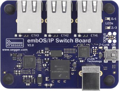
하드웨어
- MK66FN2M0VMD18 MCU: 180 MHz, 2 MB flash, 256 KB RAM, low-power, crystal-less USB
- Micro-B USB connector를 갖춘 dual-role USB interface
- User LED 2개
- Programming용 on-board J-Link-OB debug probe
- RJ45 connector 3개가 연결된 Micrel/Microchip KSZ8794CNX Ethernet switch
K66F SoC와 board 자료는 K66F product page, datasheet, reference manual, IP-K66F page, user guide, schematic에서 확인할 수 있습니다.
지원 기능
ip_k66f board configuration은 다음 hardware 기능을 지원합니다.
| Interface | Controller | Driver / Component |
|---|---|---|
| NVIC | on-chip | nested vector interrupt controller |
| SYSTICK | on-chip | systick |
| PINMUX | on-chip | pinmux |
| GPIO | on-chip | gpio |
| WATCHDOG | on-chip | watchdog |
| FLASH | on-chip | SoC flash |
| RTC | on-chip | rtc |
기본 configuration은 boards/segger/ip_k66f/ip_k66f_defconfig에 있습니다. Micrel/Microchip KSZ8794CNX Ethernet switch도 지원하며 Zephyr dsa sample에서 사용할 수 있습니다.
연결과 I/O
K66F SoC에는 pinmux/GPIO controller pair가 다섯 개 있습니다.
| Name | Function | Usage |
|---|---|---|
| PTA8 | GPIO | Red LED |
| PTA10 | GPIO | RED LED |
System clock
K66F SoC는 board의 12 MHz low-gain crystal oscillator와 on-chip PLL을 사용해 180 MHz system clock을 생성하도록 설정됩니다.
Serial port
K66F SoC에는 UART 6개가 있지만 어느 것도 사용하지 않습니다.
Programming과 debugging
Debug probe 설정
Debug probe는 board flashing과 debugging 모두에 사용됩니다. 이 board는 기본적으로 OpenSDA J-Link on-board debug probe를 사용하도록 설정됩니다.
J-Link debug host tool을 설치하고 search path에 포함합니다. OpenSDA J-Link Generic Firmware for V3.2 Bootloader를 programming합니다. SEGGER가 이 board 전용 OpenSDA J-Link firmware도 제공하지만 DAPLink bootloader와 호환되지 않는다는 점에 주의합니다.
기본 flasher는 내장 SEGGER J-Link interface를 사용하는 jlink입니다.
Flashing
blinky application 예제입니다.
west build -b ip_k66f samples/basic/blinky
west flash
Red LED0가 1초 간격으로 깜박여야 합니다.
Debugging
blinky application을 build한 뒤 debugger에서 단계별로 실행합니다.
west debugSerial console
ip_k66f board는 serial console 제공에 SEGGER RTT console만 사용하며 physical serial port는 없습니다.
첫 번째 console에서 다음 명령을 실행합니다.
/opt/SEGGER/JLink_V664/JLinkRTTLogger -Device MK66FN2M0XXX18 -RTTChannel 1 -if SWD -Speed 4000 ~/rtt.log
다른 console에서는 다음 명령으로 연결합니다.
nc localhost 19021
Source
출처
영어 원문에는 문단, 문서 지시문, 표, 코드, 코드 심벌, 경로를 그대로 보존했습니다.