Part 1
요약·해설
기본판과 Sense 차이, radio/QSPI driver, RGB LED pin, UF2와 SWD debug 경계, 두 target의 hello_world·blinky·USB shell 명령을 설명합니다.
nRF52840 · Cortex-M4F
2 MB QSPI flash
LSM6DS3TR-C · PDM mic
UF2 · SWD · J-Link · BlackMagic
Part 2
접을 수 있는 영어 원문 전체
영어 원문 전체 펼치기
1DC7D3ABC242030B3FDF131BCAA3B6F15E13D525D959A19501A64AA262133C21
.. _xiao_ble:

XIAO BLE (Sense)
################

Overview
********

The Seeed XIAO BLE (Sense) is a tiny (21 mm x 17.5 mm) Nordic Semiconductor
nRF52840 ARM Cortex-M4F development board with onboard LEDs, USB port, QSPI
flash, battery charger, and range of I/O broken out into 14 pins.

.. figure:: ../../../../../../../boards/seeed/xiao_ble/doc/img/xiao_ble.jpg
     :align: center
     :alt: XIAO BLE

Hardware
********

- Nordic nRF52840 Cortex-M4F processor at 64MHz
- 2MB QSPI Flash
- RGB LED
- USB Type-C Connector, nRF52840 acting as USB device
- Battery charger BQ25101
- Reset button
- Bluetooth antenna
- LSM6DS3TR-C 6D IMU (3D accelerometer and 3D gyroscope) (XIAO BLE Sense only)
- PDM microphone (XIAO BLE Sense only)

Supported Features
==================

The xiao_ble board configuration supports the following hardware features:

+-----------+------------+----------------------+
| Interface | Controller | Driver/Component     |
+===========+============+======================+
| ADC       | on-chip    | adc                  |
+-----------+------------+----------------------+
| CLOCK     | on-chip    | clock_control        |
+-----------+------------+----------------------+
| FLASH     | on-chip    | flash, QSPI flash    |
+-----------+------------+----------------------+
| GPIO      | on-chip    | gpio                 |
+-----------+------------+----------------------+
| I2C(M)    | on-chip    | i2c                  |
+-----------+------------+----------------------+
| MPU       | on-chip    | arch/arm             |
+-----------+------------+----------------------+
| NVIC      | on-chip    | arch/arm             |
+-----------+------------+----------------------+
| PWM       | on-chip    | pwm                  |
+-----------+------------+----------------------+
| RADIO     | on-chip    | Bluetooth,           |
|           |            | ieee802154           |
+-----------+------------+----------------------+
| RTC       | on-chip    | system clock         |
+-----------+------------+----------------------+
| SPI(M/S)  | on-chip    | spi                  |
+-----------+------------+----------------------+
| UART      | on-chip    | serial               |
+-----------+------------+----------------------+
| USB       | on-chip    | usb                  |
+-----------+------------+----------------------+
| WDT       | on-chip    | watchdog             |
+-----------+------------+----------------------+

Other hardware features have not been enabled yet for this board.

Connections and IOs
===================

The `XIAO BLE wiki`_ has detailed information about the board including
`pinouts`_ and the `schematic`_.

LED
---

* LED1 (red) = P0.26
* LED2 (green) = P0.30
* LED3 (blue) = P0.06

Programming and Debugging
*************************

The XIAO BLE ships with the `Adafruit nRF52 Bootloader`_ which supports flashing
using `UF2`_. Doing so allows easy flashing of new images, but does not support
debugging the device. For debugging please use `External Debugger`_.

UF2 Flashing
============

To enter the bootloader, connect the USB port of the XIAO BLE to your host, and
double tap the reset botton to the left of the USB connector. A mass storage
device named `XIAO BLE` should appear on the host. Using the command line, or
your file manager copy the `zephyr/zephyr.uf2` file from your build to the base
of the `XIAO BLE` mass storage device. The XIAO BLE will automatically reset
and launch the newly flashed application.

External Debugger
=================

In order to support debugging the device, instead of using the bootloader, you
can use an :ref:`External Debug Probe <debug-probes>`. To flash and debug Zephyr
applications you need to use `Seeeduino XIAO Expansion Board`_ or solder an SWD
header onto the back side of the board.

For Segger J-Link debug probes, follow the instructions in the
:ref:`jlink-external-debug-probe` page to install and configure all the
necessary software.

Flashing
--------

Setup and connect a supported debug probe (JLink, instructions at :ref:`jlink-external-debug-probe` or
BlackMagic Probe). Then build and flash applications as
usual (see :ref:`build_an_application` and :ref:`application_run` for more
details).

Here is an example for the :ref:`hello_world` application.

First, run your favorite terminal program to listen for output.

.. code-block:: console

   $ minicom -D <tty_device> -b 115200

Replace :code:`<tty_device>` with the port where the board XIAO BLE
can be found. For example, under Linux, :code:`/dev/ttyACM0`.

Then build and flash the application in the usual way. Just add
``CONFIG_BOOT_DELAY=5000`` to the configuration, so that USB CDC ACM is
initialized before any text is printed, as below:

.. tabs::

   .. group-tab:: XIAO BLE

      .. zephyr-app-commands::
         :zephyr-app: samples/hello_world
         :board: xiao_ble
         :goals: build flash
         :gen-args: -DCONFIG_BOOT_DELAY=5000

   .. group-tab:: XIAO BLE Sense

      .. zephyr-app-commands::
         :zephyr-app: samples/hello_world
         :board: xiao_ble/nrf52840/sense
         :goals: build flash
         :gen-args: -DCONFIG_BOOT_DELAY=5000

Debugging
---------

Refer to the :ref:`jlink-external-debug-probe` page to learn about debugging
boards with a Segger IC.

Debugging using a BlackMagic Probe is also supported.

Testing the LEDs in the XIAO BLE (Sense)
****************************************

There is a sample that allows to test that LEDs on the board are working
properly with Zephyr:

.. tabs::

   .. group-tab:: XIAO BLE

      .. zephyr-app-commands::
         :zephyr-app: samples/basic/blinky
         :board: xiao_ble
         :goals: build flash

   .. group-tab:: XIAO BLE Sense

      .. zephyr-app-commands::
         :zephyr-app: samples/basic/blinky
         :board: xiao_ble/nrf52840/sense
         :goals: build flash

You can build and flash the examples to make sure Zephyr is running correctly on
your board. The LED definitions can be found in
:zephyr_file:`boards/seeed/xiao_ble/xiao_ble_common.dtsi`.

Testing shell over USB in the XIAO BLE (Sense)
**********************************************

There is a sample that allows to test shell interface over USB CDC ACM interface
with Zephyr:

.. tabs::

   .. group-tab:: XIAO BLE

      .. zephyr-app-commands::
         :zephyr-app: samples/subsys/shell/shell_module
         :board: xiao_ble
         :goals: build flash

   .. group-tab:: XIAO BLE Sense

      .. zephyr-app-commands::
         :zephyr-app: samples/subsys/shell/shell_module
         :board: xiao_ble/nrf52840/sense
         :goals: build flash

References
**********

.. target-notes::

.. _XIAO BLE wiki: https://wiki.seeedstudio.com/XIAO_BLE/
.. _pinouts: https://wiki.seeedstudio.com/XIAO_BLE/#hardware-overview
.. _schematic: https://wiki.seeedstudio.com/XIAO_BLE/#resources
.. _Seeeduino XIAO Expansion Board: https://wiki.seeedstudio.com/Seeeduino-XIAO-Expansion-Board/
.. _Adafruit nRF52 Bootloader: https://github.com/adafruit/Adafruit_nRF52_Bootloader
.. _UF2: https://github.com/microsoft/uf2
Part 3
한국어 전문 번역
개요
Seeed XIAO BLE(Sense)는 21 mm × 17.5 mm 크기의 작은 Nordic Semiconductor nRF52840 ARM Cortex-M4F development board입니다. On-board LED, USB port, QSPI flash, battery charger와 14개 pin으로 외부에 노출된 여러 I/O를 제공합니다.
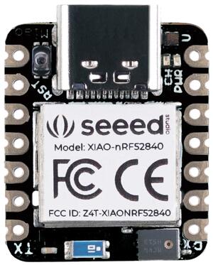
하드웨어
- 64 MHz Nordic nRF52840 Cortex-M4F processor
- 2 MB QSPI flash
- RGB LED
- USB Type-C connector; nRF52840이 USB device로 동작
- BQ25101 battery charger
- Reset button
- Bluetooth antenna
- LSM6DS3TR-C 6D IMU: 3D accelerometer + 3D gyroscope, XIAO BLE Sense 전용
- PDM microphone, XIAO BLE Sense 전용
지원 기능
xiao_ble board configuration은 다음 hardware 기능을 지원합니다.
| Interface | Controller | Driver / Component |
|---|---|---|
| ADC | on-chip | adc |
| CLOCK | on-chip | clock_control |
| FLASH | on-chip | flash, QSPI flash |
| GPIO | on-chip | gpio |
| I2C(M) | on-chip | i2c |
| MPU | on-chip | arch/arm |
| NVIC | on-chip | arch/arm |
| PWM | on-chip | pwm |
| RADIO | on-chip | Bluetooth, ieee802154 |
| RTC | on-chip | system clock |
| SPI(M/S) | on-chip | spi |
| UART | on-chip | serial |
| USB | on-chip | usb |
| WDT | on-chip | watchdog |
그 밖의 hardware 기능은 아직 이 board에서 활성화되지 않았습니다.
연결과 I/O
XIAO BLE Wiki에는 pinout과 schematic을 포함한 상세 정보가 있습니다.
LED
LED1 (red) = P0.26LED2 (green) = P0.30LED3 (blue) = P0.06
Programming과 debugging
XIAO BLE는 Adafruit nRF52 Bootloader가 설치된 상태로 출하되며 UF2 flashing을 지원합니다. UF2는 새 image를 쉽게 flash할 수 있지만 device debugging은 지원하지 않으므로 debugging에는 외부 debugger를 사용합니다.
UF2 flashing
XIAO BLE의 USB port를 host에 연결하고 USB connector 왼쪽의 reset button을 두 번 누릅니다. Host에 XIAO BLE이라는 mass-storage device가 나타나야 합니다. Command line이나 file manager로 build 결과의 zephyr/zephyr.uf2를 XIAO BLE drive 최상위에 복사합니다. Board는 자동으로 reset하고 새 application을 실행합니다.
외부 debugger
Bootloader 대신 외부 debug probe를 사용하면 device debugging을 지원할 수 있습니다. Zephyr application을 flash하고 debug하려면 Seeeduino XIAO Expansion Board를 사용하거나 board 뒷면에 SWD header를 납땜합니다.
Segger J-Link debug probe는 필요한 software를 설치하고 external probe로 설정해야 합니다. BlackMagic Probe도 지원됩니다.
Flashing
J-Link 또는 BlackMagic Probe처럼 지원되는 debug probe를 설정하고 연결한 뒤 일반적인 방식으로 application을 build하고 flash합니다.
먼저 terminal program으로 출력을 기다립니다.
$ minicom -D <tty_device> -b 115200<tty_device>를 XIAO BLE가 연결된 port로 바꿉니다. Linux에서는 예를 들어 /dev/ttyACM0입니다.
USB CDC ACM이 text 출력 전에 초기화되도록 configuration에 CONFIG_BOOT_DELAY=5000을 추가하고 build/flash합니다.
XIAO BLE
west build -b xiao_ble samples/hello_world -- -DCONFIG_BOOT_DELAY=5000
west flash
XIAO BLE Sense
west build -b xiao_ble/nrf52840/sense samples/hello_world -- -DCONFIG_BOOT_DELAY=5000
west flash
Debugging
Segger IC가 있는 board의 debugging은 J-Link external debug probe 절차를 따릅니다. BlackMagic Probe를 이용한 debugging도 지원됩니다.
XIAO BLE(Sense) LED 시험
blinky sample로 board LED가 Zephyr에서 올바르게 작동하는지 확인할 수 있습니다.
XIAO BLE
west build -b xiao_ble samples/basic/blinky
west flash
XIAO BLE Sense
west build -b xiao_ble/nrf52840/sense samples/basic/blinky
west flash
예제를 build하고 flash해 Zephyr가 board에서 올바르게 실행되는지 확인할 수 있습니다. LED 정의는 boards/seeed/xiao_ble/xiao_ble_common.dtsi에 있습니다.
XIAO BLE(Sense) USB shell 시험
shell_module sample로 USB CDC ACM interface를 통한 Zephyr shell을 시험할 수 있습니다.
XIAO BLE
west build -b xiao_ble samples/subsys/shell/shell_module
west flash
XIAO BLE Sense
west build -b xiao_ble/nrf52840/sense samples/subsys/shell/shell_module
west flash
참고 자료
Source
출처
영어 원문에는 문단, 문서 지시문, 표, 코드, 코드 심벌, 경로를 그대로 보존했습니다.