Part 1
요약·해설
풍부한 물리 hardware와 Zephyr 지원 범위를 구분하고, RTC tick 제약, USB CDC console, UF2 mass-storage flash, SWD/J-Link 배선을 설명합니다.
ATSAMD51P19 · Cortex-M4F
2.4-inch LCD
RTL8720DN · Wi-Fi · BLE 5.0
UF2 · SWD · J-Link
Part 2
접을 수 있는 영어 원문 전체
영어 원문 전체 펼치기
03F43B92592ABED9EB176D61A30FC73677986D4331584E390B855CA630336F07
.. _wio_terminal:

Wio Terminal
############

Overview
********

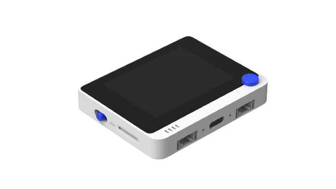
The Wio Terminal is a small (72 mm x 57 mm x 12 mm) and powerful ARM board with
wireless connectivity (2.4G/5G dual-band Wi-Fi and BLE 5.0), LCD display,
USB C port, FPC connector, microSD card slot, Raspberry Pi compatible 40-pins
header and 2 Grove connectors.

.. image:: ../../../../../../../boards/seeed/wio_terminal/doc/img/wio_terminal.png
     :width: 500px
     :align: center
     :alt: Seeed Studio Wio Terminal

Hardware
********

- ATSAMD51P19 ARM Cortex-M4F processor at 120 MHz
- 512 KiB flash memory and 192 KiB of RAM
- 4 MiB external flash
- MicroSD card slot
- RTL8720DN 2.4G/5G Dual Bands Wireless and BLE5.0 Combo Module
- 2.4inch LCD display
- LIS3DH accelerometer
- Microphone 1.0V-10V -42dB
- Speaker ≥78dB @10cm 4000Hz
- Light Sensor 400-1050nm
- Infrared Emitter 940nm
- GPIO 40 pin (Raspberry Pi compatible)
- 2x Grove connectors
- 1x user LED
- 3x user buttons
- 5-way user button
- Power/Reset/Boot mode switch
- Native USB port

Supported Features
==================

The wio_terminal board configuration supports the following hardware features:

.. list-table::
    :header-rows: 1

    * - Interface
      - Controller
      - Driver / Component
    * - NVIC
      - on-chip
      - Nested vector interrupt controller
    * - Flash
      - on-chip
      - Can be used with LittleFS to store files
    * - SYSTICK
      - on-chip
      - Systick
    * - WDT
      - on-chip
      - Watchdog
    * - GPIO
      - on-chip
      - I/O ports
    * - USART
      - on-chip
      - Serial port
    * - I2C
      - on-chip
      - Inter-Integrated Circuit
    * - SPI
      - on-chip
      - Serial Peripheral Interface port
    * - TRNG
      - on-chip
      - True Random Number Generator
    * - HWINFO
      - on-chip
      - Unique 128 bit serial number
    * - RTC
      - on-chip
      - Real-Time Counter
    * - USB
      - on-chip
      - USB device
    * - PWM
      - on-chip
      - PWM

Other hardware features are not currently supported by Zephyr.

The default configuration can be found in the Kconfig file
:zephyr_file:`boards/seeed/wio_terminal/wio_terminal_defconfig`.

Zephyr can use the default Cortex-M SYSTICK timer or the SAM0 specific RTC.
To use the RTC, set :kconfig:option:`CONFIG_CORTEX_M_SYSTICK=n` and set
:kconfig:option:`CONFIG_SYS_CLOCK_TICKS_PER_SEC` to no more than 32 kHZ divided
by 7, i.e. no more than 4500.

Connections and IOs
===================

The `Wio Terminal Getting started guide`_ has detailed information about the
board including `pinouts`_ and its `schematics`_.

System Clock
============

The SAMD51 MCU is configured to use the 32.768 kHz internal oscillator with the
on-chip PLL generating the 120 MHz system clock.

Serial Port
===========

Zephyr console output is available using the USB connector, which is used to
make the console available on PC as USB CDC class.

USB Device Port
===============

The SAMD51 MCU has a USB device port that can be used to communicate with a
host PC.  See the :ref:`usb-samples` sample applications for more, such as the
:zephyr:code-sample:`usb-cdc-acm` sample which sets up a virtual serial port that echos
characters back to the host PC.

Programming and Debugging
*************************

The Wio Terminal ships with an UF2 bootloader that is BOSSA compatible. The
bootloader can be entered by quickly tapping the reset button twice.

The UF2 file is generated when building the application, and it is possible to
use it to flash the target. Enter the bootloader by quickly sliding the power
button twice, and copy the UF2 file to the USB mass storage device. The device
reboots on the new firmware after the UF2 file has finished transferring.

Flashing
========

#. Build the Zephyr kernel and the :code:`button` sample application:

   .. zephyr-app-commands::
      :zephyr-app: samples/basic/button
      :board: wio_terminal
      :goals: build
      :compact:

#. Swipe the reset/power button down twice quickly to enter bootloader mode

#. Flash the image:

   .. zephyr-app-commands::
      :zephyr-app: samples/basic/button
      :board: wio_terminal
      :goals: flash
      :compact:

   You should see the blue (user) LED flashing whenever you press the third
   (counting from the top left) user button at the top of the Wio Terminal.

Debugging
=========

In addition to the built-in bootloader, the Wio Terminal can be flashed and
debugged using an SWD probe such as the Segger J-Link.

#.  Solder cables to the :code:`SWCLK`, :code:`SWDIO`, :code:`RESET`,
    :code:`GND`, and :code:`3V3` pins. See `Test with SWD`_ for more
    information.

#. Connect the board to the probe by connecting the :code:`SWCLK`,
   :code:`SWDIO`, :code:`RESET`, :code:`GND`, and :code:`3V3` pins on the
   Wio Terminal to the :code:`SWCLK`, :code:`SWDIO`, :code:`RESET`,
   :code:`GND`, and :code:`VTref` pins on the `J-Link`_.

#. Flash the image:

   .. zephyr-app-commands::
      :zephyr-app: samples/basic/button
      :board: wio_terminal
      :goals: flash
      :flash-args: -r openocd
      :compact:

#. Start debugging:

   .. zephyr-app-commands::
      :zephyr-app: samples/basic/button
      :board: wio_terminal
      :goals: debug
      :compact:

References
**********

.. target-notes::

.. _Wio Terminal Getting started guide:
   https://wiki.seeedstudio.com/Wio-Terminal-Getting-Started/

.. _pinouts:
    https://wiki.seeedstudio.com/Wio-Terminal-Getting-Started/#pinout-diagram

.. _schematics:
    https://wiki.seeedstudio.com/Wio-Terminal-Getting-Started/#resources

.. _Test with SWD:
    https://wiki.seeedstudio.com/Wio-Terminal-Getting-Started/#test-with-swd

.. _J-Link:
    https://www.segger.com/products/debug-probes/j-link/technology/interface-description/
Part 3
한국어 전문 번역
개요
Wio Terminal은 72 mm × 57 mm × 12 mm 크기의 작고 강력한 ARM board입니다. 2.4/5 GHz dual-band Wi-Fi와 BLE 5.0 wireless, LCD display, USB-C port, FPC connector, microSD card slot, Raspberry Pi-compatible 40-pin header, Grove connector 2개를 갖습니다.
하드웨어
- 120 MHz ATSAMD51P19 ARM Cortex-M4F processor
- 512 KiB flash + 192 KiB RAM
- 4 MiB external flash
- microSD card slot
- RTL8720DN 2.4/5 GHz dual-band wireless + BLE 5.0 combo module
- 2.4-inch LCD display
- LIS3DH accelerometer
- Microphone: 1.0-10 V, -42 dB
- Speaker: ≥78 dB at 10 cm, 4000 Hz
- Light sensor: 400-1050 nm
- Infrared emitter: 940 nm
- Raspberry Pi-compatible 40-pin GPIO
- Grove connector 2개
- User LED 1개
- User button 3개
- 5-way user button
- Power/reset/boot-mode switch
- Native USB port
지원 기능
wio_terminal board configuration은 다음 hardware 기능을 지원합니다.
| Interface | Controller | Driver / Component |
|---|---|---|
| NVIC | on-chip | Nested vector interrupt controller |
| Flash | on-chip | LittleFS file storage에 사용 가능 |
| SYSTICK | on-chip | Systick |
| WDT | on-chip | Watchdog |
| GPIO | on-chip | I/O ports |
| USART | on-chip | Serial port |
| I2C | on-chip | Inter-Integrated Circuit |
| SPI | on-chip | Serial Peripheral Interface port |
| TRNG | on-chip | True Random Number Generator |
| HWINFO | on-chip | Unique 128-bit serial number |
| RTC | on-chip | Real-Time Counter |
| USB | on-chip | USB device |
| PWM | on-chip | PWM |
그 밖의 hardware 기능은 현재 Zephyr에서 지원하지 않습니다. 기본 configuration은 boards/seeed/wio_terminal/wio_terminal_defconfig에 있습니다.
연결과 I/O
Wio Terminal getting-started guide에 pinout과 schematic을 포함한 상세 정보가 있습니다.
System clock
SAMD51 MCU는 32.768 kHz internal oscillator를 사용하며 on-chip PLL이 120 MHz system clock을 생성하도록 설정됩니다.
Serial port
Zephyr console output은 USB connector를 사용하며 PC에서 USB CDC class console로 나타납니다.
USB device port
SAMD51 MCU의 USB device port는 host PC와 통신하는 데 사용할 수 있습니다. Zephyr usb-cdc-acm sample은 host PC에 character를 되돌려 보내는 virtual serial port를 구성합니다.
Programming과 debugging
Wio Terminal은 BOSSA-compatible UF2 bootloader가 설치된 상태로 출하됩니다. Reset button을 빠르게 두 번 누르면 bootloader에 진입합니다.
Application을 build하면 UF2 file이 생성되며 이를 target flash에 사용할 수 있습니다. Power button을 빠르게 두 번 밀어 bootloader에 진입한 뒤 USB mass-storage device에 UF2 file을 복사합니다. 전송이 끝나면 device가 새 firmware로 reboot합니다.
Flashing
- Zephyr kernel과
buttonsample application을 build합니다.west build -b wio_terminal samples/basic/button - Reset/power button을 아래로 빠르게 두 번 밀어 bootloader mode에 들어갑니다.
- Image를 flash합니다.
west flashWio Terminal 상단의 user button 중 왼쪽 위에서 세 번째 button을 누를 때마다 blue user LED가 깜박여야 합니다.
Debugging
내장 bootloader 외에도 Segger J-Link 같은 SWD probe로 Wio Terminal을 flash하고 debug할 수 있습니다.
SWCLK,SWDIO,RESET,GND,3V3pin에 cable을 납땜합니다. 자세한 내용은 Test with SWD를 참고합니다.- Wio Terminal의
SWCLK,SWDIO,RESET,GND,3V3를 J-Link의SWCLK,SWDIO,RESET,GND,VTref에 각각 연결합니다. - OpenOCD runner로 image를 flash합니다.
west flash -r openocd - Debugging을 시작합니다.
west debug
참고 자료
Source
출처
영어 원문에는 문단, 문서 지시문, 표, 코드, 코드 심벌, 경로를 그대로 보존했습니다.