Part 1
요약·해설
Mini 고유 LED·battery·mounting 구성, 6개 peripheral mapping, 복구 불가 RDP regression 경고, 외부 SWD runner와 serial/debug 절차를 설명합니다.
STM32WLE5JC · Cortex-M4
SX126X · 150-960 MHz
USB-C · battery pins · M2 × 4
RDP 1 → 0 erases factory firmware
Part 2
접을 수 있는 영어 원문 전체
영어 원문 전체 펼치기
7C5B52C6577D35026D23106D601FB73D962BA6A4484B0F3E771CFFCAE0C41B64
.. _lora_e5_mini:

Seeed Studio LoRa-E5 mini
#########################

Overview
********

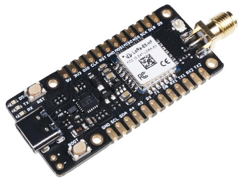
LoRa-E5 mini is a compacted-sized development board suitable for the rapid
testing and building of small-sized LoRa device, exposing all capabilities of
Seeed Studio LoRa-E5 STM32WLE5JC module.

.. image:: ../../../../../../../boards/seeed/lora_e5_mini/doc/img/lora_e5_mini.jpg
   :align: center
   :alt: LoRa-E5 mini

Hardware
********

The boards' LoRa-E5 Module packages a STM32WLE5JC SOC, a 32MHz TCXO,
and a 32.768kHz crystal oscillator in a 28-pin SMD package.
This STM32WLEJC SOC is powered by ARM Cortex-M4 core and integrates Semtech
SX126X LoRa IP to support (G)FSK, BPSK, (G)MSK, and LoRa modulations.

- LoRa-E5 STM32WLE5JC Module with STM32WLE5JC multiprotocol LPWAN single-core
  32-bit microcontroller (Arm® Cortex®-M4 at 48 MHz) in 28-pin SMD package
  featuring:

  - Ultra-low-power MCU
  - RF transceiver (150 MHz to 960 MHz frequency range) supporting LoRa®,
    (G)FSK, (G)MSK, and BPSK modulations
  - 256-Kbyte Flash memory and 64-Kbyte SRAM
  - Hardware encryption AES256-bit and a True random number generator

- 1 user LED
- 2 serial communication (RX/TX) LEDs
- 1 boot/user and 1 reset push-button
- 32.768 kHz LSE crystal oscillator
- 32 MHz HSE oscillator
- Board connectors:

  - USB Type-C connector
  - +/- (battery) power input pins (3-5V)
  - SMA-K and IPEX antenna connectors

- Delivered with SMA antenna (per default IPEX connector is disconnected)
- Flexible power-supply options: USB Type C or 3-5V battery soldered to +/- pins
- Suitable for rapid prototyping of end nodes based on LoRaWAN, Sigfox, wM-Bus,
  and many other proprietary protocols
- All GPIOs led out from the LoRa-E5 STM32WLE5JC module
- 4x M2 mounting holes

More information about the board can be found at the `LoRa-E5 mini Wiki`_.

More information about LoRa-E5 STM32WLE5JC Module can be found here:

- `LoRa-E5 STM32WLE5JC Module Wiki`_
- `LoRa-E5 STM32WLE5JC Module datasheet`_
- `STM32WLE5JC datasheet`_
- `STM32WLE5JC reference manual`_
- `STM32WLE5JC on www.st.com`_

Supported Features
==================

The Zephyr LoRa-E5 mini configuration supports the following hardware features:

+-----------+------------+-------------------------------------+
| Interface | Controller | Driver/Component                    |
+===========+============+=====================================+
| ADC       | on-chip    | adc                                 |
+-----------+------------+-------------------------------------+
| AES       | on-chip    | crypto                              |
+-----------+------------+-------------------------------------+
| COUNTER   | on-chip    | rtc                                 |
+-----------+------------+-------------------------------------+
| CLOCK     | on-chip    | reset and clock control             |
+-----------+------------+-------------------------------------+
| FLASH     | on-chip    | flash                               |
+-----------+------------+-------------------------------------+
| GPIO      | on-chip    | gpio                                |
+-----------+------------+-------------------------------------+
| I2C       | on-chip    | i2c                                 |
+-----------+------------+-------------------------------------+
| MPU       | on-chip    | arch/arm                            |
+-----------+------------+-------------------------------------+
| NVIC      | on-chip    | arch/arm                            |
+-----------+------------+-------------------------------------+
| PINMUX    | on-chip    | pinmux                              |
+-----------+------------+-------------------------------------+
| RADIO     | on-chip    | LoRa                                |
+-----------+------------+-------------------------------------+
| SPI       | on-chip    | spi                                 |
+-----------+------------+-------------------------------------+
| UART      | on-chip    | serial port-polling;                |
|           |            | serial port-interrupt               |
+-----------+------------+-------------------------------------+
| WATCHDOG  | on-chip    | independent watchdog                |
+-----------+------------+-------------------------------------+

Other hardware features are not yet supported on this Zephyr port.

The default configuration can be found in:

- :zephyr_file:`boards/seeed/lora_e5_mini/lora_e5_mini_defconfig`
- :zephyr_file:`boards/seeed/lora_e5_mini/lora_e5_mini.dts`


Connections and IOs
===================

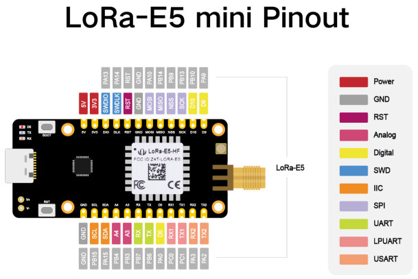
LoRa-E5 mini has 4 GPIO controllers. These controllers are responsible for pin
muxing, input/output, pull-up, etc.

Available pins:
---------------

.. image:: ../../../../../../../boards/seeed/lora_e5_mini/doc/img/lora_e5_mini_pinout.jpg
      :align: center
      :alt: LoRa-E5 mini Pinout

Default Zephyr Peripheral Mapping:
----------------------------------

- USART_1 TX  : PB6
- USART_1 RX  : PB7
- I2C_2_SCL   : PB15
- I2C_2_SDA   : PA15
- BOOT_PB     : PB13
- LED_1       : PB5

System Clock
------------

LoRa-E5 mini board System Clock could be driven by the low-power internal (MSI),
High-speed internal (HSI) or High-speed external (HSE) oscillator, as well as
main PLL clock. By default System clock is driven by the MSI clock at 48MHz.

Programming and Debugging
*************************

Applications for the ``lora_e5_mini`` board configuration can be built the
usual way (see :ref:`build_an_application`).

In the factory the module is flashed with an DFU bootloader, an AT command
firmware, and the read protection level 1 is enabled.
So before you can program a Zephyr application to the module for the first time
you have to reset the read protection to level 0.
In case you use an st-link debugger you can use the STM32CubeProgrammer GUI to
set the RDP option byte to ``AA``,
or use the STM32_Programmer_CLI passing the ``--readunprotect`` command
to perform this read protection regression.
The RDP level 1 to RDP level 0 regression will erase the factory programmed AT
firmware, from which seeed studio has neither released the source code nor a binary.
Also, note that on the module the ``BOOT0`` pin of the SOC is not accessible,
so the system bootloader will only be executed if configured in the option bytes.

Flashing
========

The LoRa-E5 mini does not include a on-board debug probe.
But the module can be debugged by connecting an external debug probe to the
2.54mm header.
Depending on the external probe used, ``openocd``, the ``stm32cubeprogrammer``,
``pyocd``, ``blackmagic``, or ``jlink`` runner can be used to flash the board.
Additional notes:

- Pyocd: For STM32WL support Pyocd needs additional target information, which
  can be installed by adding "pack" support with the following pyocd command:

.. code-block:: console

   $ pyocd pack --update
   $ pyocd pack --install stm32wl

Flashing an application to LoRa-E5 mini
---------------------------------------

Connect the LoRa-E5 to your host computer using the external debug probe.
Then build and flash an application. Here is an example for the
:ref:`hello_world` application.

Run a serial host program to connect with your board:
Per default the console on ``usart1`` is available on the USB Type C connector
via the built-in USB to UART converter.

.. code-block:: console

   $ picocom --baud 115200 /dev/ttyACM0

Then build and flash the application.

.. zephyr-app-commands::
   :zephyr-app: samples/hello_world
   :board: lora_e5_mini
   :goals: build flash

Debugging
=========

You can debug an application in the usual way. Here is an example for the
:zephyr:code-sample:`blinky` application.

.. zephyr-app-commands::
   :zephyr-app: samples/basic/blinky
   :board: lora_e5_mini
   :maybe-skip-config:
   :goals: debug

.. _LoRa-E5 mini Wiki:
   https://wiki.seeedstudio.com/LoRa_E5_mini/

.. _LoRa-E5 STM32WLE5JC Module Wiki:
   https://wiki.seeedstudio.com/LoRa-E5_STM32WLE5JC_Module/

.. _LoRa-E5 STM32WLE5JC Module datasheet:
    https://files.seeedstudio.com/products/317990687/res/LoRa-E5%20module%20datasheet_V1.0.pdf

.. _STM32WLE5JC on www.st.com:
   https://www.st.com/en/microcontrollers-microprocessors/stm32wle5jc.html

.. _STM32WLE5JC datasheet:
   https://www.st.com/resource/en/datasheet/stm32wle5jc.pdf

.. _STM32WLE5JC reference manual:
   https://www.st.com/resource/en/reference_manual/dm00530369-stm32wlex-advanced-armbased-32bit-mcus-with-subghz-radio-solution-stmicroelectronics.pdf
Part 3
한국어 전문 번역
개요
LoRa-E5 mini는 소형 LoRa device를 빠르게 시험하고 제작하기에 적합한 compact development board입니다. Seeed Studio LoRa-E5 STM32WLE5JC module의 모든 기능을 외부에 제공합니다.
하드웨어
LoRa-E5 module은 28-pin SMD package 안에 STM32WLE5JC SoC, 32 MHz TCXO, 32.768 kHz crystal oscillator를 넣습니다. ARM Cortex-M4 core 기반 STM32WLE5JC는 Semtech SX126X LoRa IP를 통합해 (G)FSK, BPSK, (G)MSK, LoRa modulation을 지원합니다.
- LoRa-E5 STM32WLE5JC module: 48 MHz ARM Cortex-M4 single-core multiprotocol LPWAN MCU, 28-pin SMD package
- Ultra-low-power MCU
- 150-960 MHz RF transceiver: LoRa, (G)FSK, (G)MSK, BPSK modulation
- 256 KB flash + 64 KB SRAM
- AES-256 hardware encryption + true random-number generator
- User LED 1개
- Serial communication RX/TX LED 2개
- Boot/user push-button 1개 + reset push-button 1개
- 32.768 kHz LSE crystal oscillator
- 32 MHz HSE oscillator
- USB Type-C connector
- Battery 전원 입력 +/- pin: 3-5 V
- SMA-K와 IPEX antenna connector
- 기본 제공 SMA antenna; 기본 상태에서 IPEX connector는 분리됨
- 전원 선택: USB Type-C 또는 +/- pin에 납땜한 3-5 V battery
- LoRaWAN, Sigfox, wM-Bus 및 proprietary protocol end node의 rapid prototyping에 적합
- LoRa-E5 STM32WLE5JC module의 모든 GPIO 외부 노출
- M2 mounting hole 4개
상세 자료는 LoRa-E5 mini Wiki, module Wiki, module datasheet, STM32WLE5JC datasheet, reference manual, ST product page에서 확인할 수 있습니다.
지원 기능
Zephyr LoRa-E5 mini configuration은 다음 hardware 기능을 지원합니다.
| Interface | Controller | Driver / Component |
|---|---|---|
| ADC | on-chip | adc |
| AES | on-chip | crypto |
| COUNTER | on-chip | rtc |
| CLOCK | on-chip | reset and clock control |
| FLASH | on-chip | flash |
| GPIO | on-chip | gpio |
| I2C | on-chip | i2c |
| MPU | on-chip | arch/arm |
| NVIC | on-chip | arch/arm |
| PINMUX | on-chip | pinmux |
| RADIO | on-chip | LoRa |
| SPI | on-chip | spi |
| UART | on-chip | serial port-polling; serial port-interrupt |
| WATCHDOG | on-chip | independent watchdog |
그 밖의 hardware 기능은 아직 이 Zephyr port에서 지원하지 않습니다. 기본 configuration은 boards/seeed/lora_e5_mini/lora_e5_mini_defconfig와 boards/seeed/lora_e5_mini/lora_e5_mini.dts에 있습니다.
연결과 I/O
LoRa-E5 mini에는 GPIO controller 4개가 있으며 pin muxing, input/output, pull-up 등을 담당합니다.
사용 가능한 pin
기본 Zephyr peripheral mapping
USART_1 TX : PB6USART_1 RX : PB7I2C_2_SCL : PB15I2C_2_SDA : PA15BOOT_PB : PB13LED_1 : PB5
System clock
LoRa-E5 mini system clock은 low-power internal MSI, high-speed internal HSI, high-speed external HSE oscillator 또는 main PLL clock으로 구동할 수 있습니다. 기본 system clock은 48 MHz MSI clock입니다.
Programming과 debugging
lora_e5_mini board configuration용 application은 일반적인 Zephyr 방식으로 build할 수 있습니다.
Flashing
LoRa-E5 mini에는 on-board debug probe가 없습니다. 2.54 mm header에 외부 debug probe를 연결해 debug합니다. Probe에 따라 openocd, stm32cubeprogrammer, pyocd, blackmagic, jlink runner로 flash할 수 있습니다.
pyOCD에서 STM32WL을 지원하려면 다음 명령으로 추가 target pack 정보를 설치해야 합니다.
$ pyocd pack --update
$ pyocd pack --install stm32wl
LoRa-E5 mini에 application flash
외부 debug probe를 사용해 LoRa-E5를 host computer에 연결한 다음 application을 build하고 flash합니다. 다음은 hello_world 예제입니다.
기본적으로 usart1 console은 내장 USB-to-UART converter를 거쳐 USB Type-C connector에서 사용할 수 있습니다. Serial host program으로 연결합니다.
$ picocom --baud 115200 /dev/ttyACM0그런 다음 application을 build하고 flash합니다.
west build -b lora_e5_mini samples/hello_world
west flash
Debugging
Application은 일반적인 방식으로 debug할 수 있습니다. 다음은 blinky application 예제입니다.
west build -b lora_e5_mini samples/basic/blinky
west debug
참고 자료
Source
출처
영어 원문에는 문단, 문서 지시문, 표, 코드, 코드 심벌, 경로를 그대로 보존했습니다.