Part 1
요약·해설
센서와 Zephyr driver 연결, GPIO와 debug connector pinout, DEVKIT/SWD flashing, LED와 button 검증 sample을 설명합니다.
Nordic nRF52832
BME280 · LIS2DH12
Bluetooth Low Energy · NFC-A
DEVKIT · SWDIO · SWDCLK
Part 2
접을 수 있는 영어 원문 전체
영어 원문 전체 펼치기
3C2623A5B15AAC99EFAD4710CDABEB0E409AD290963FF6164F29825F365AA661
.. _ruuvi_ruuvitag:

Ruuvi RuuviTag
##############

Overview
********

RuuviTag is an advanced battery-operated open-source Bluetooth
enabled sensor beacon platform capable of sending temperature, humidity,
pressure, and motion information over Bluetooth Low Energy.

.. figure:: ../../../../../../../boards/ruuvi/ruuvitag/doc/img/ruuvitag.jpg
     :align: center
     :alt: RUUVI RuuviTag

     RUUVI RuuviTag (Credit: https://ruuvi.com/)

More information about the board can be found at the
`ruuvitag website`_.

Hardware
********

RuuviTag's have the following physical features:

* Nordic Semiconductor nRF52832 System-on-Chip
* STMicroelectronics LIS2DH12 accelerometer
* Bosch BME 280 temperature + relative air humidity + air pressure sensor
* NFC™-A tag antenna
* 1000mAh CR2477 battery
* 2 buttons
* 1 Green LED
* 1 Red LED
* IP67 Enclosure
* Long range RF antenna

Supported Features
==================

+-----------+------------+----------------------+
| Interface | Controller | Driver/Component     |
+===========+============+======================+
| ADC       | on-chip    | adc                  |
+-----------+------------+----------------------+
| CLOCK     | on-chip    | clock_control        |
+-----------+------------+----------------------+
| FLASH     | on-chip    | flash                |
+-----------+------------+----------------------+
| GPIO      | on-chip    | gpio                 |
+-----------+------------+----------------------+
| MPU       | on-chip    | arch/arm             |
+-----------+------------+----------------------+
| NVIC      | on-chip    | arch/arm             |
+-----------+------------+----------------------+
| RADIO     | on-chip    | Bluetooth            |
+-----------+------------+----------------------+
| RTC       | on-chip    | system clock         |
+-----------+------------+----------------------+
| SPI       | on-chip    | spi                  |
+-----------+------------+----------------------+
| UART      | on-chip    | serial               |
+-----------+------------+----------------------+
| WDT       | on-chip    | watchdog             |
+-----------+------------+----------------------+
| Humidity, | on-board   | bme280               |
| Temp & Air|            |                      |
| Pressure  |            |                      |
+-----------+------------+----------------------+
| Acc       | on-board   | lis2dh12             |
+-----------+------------+----------------------+

Connections and IOs
===================

LED
---

* LED0 (red) = P0.17
* LED1 (green) = P0.19

Push buttons
------------

* BUTTON0 = SW1 = P0.13

Pin descriptions
----------------

.. figure:: ../../../../../../../boards/ruuvi/ruuvitag/doc/img/pinout.jpg
     :align: center
     :alt: RUUVI Pinout

* 2 = P0.29 = SPI_SCK
* 3 = P0.28 = SPI_MISO
* 10 = P0.04 = GPIO (can be used as a GPIO / ADC pin)
* 11 = P0.05 = GPIO (can be used as a GPIO / ADC pin)
* 12 = P0.25 = SPI_MOSI
* 13 = P0.19 = LED2 (green) / GPIO (can be used as a GPIO pin but the LED will blink)
* 14 = P0.17 = LED1 (red) / GPIO (can be used as a GPIO pin but the LED will blink)
* 15 = P0.13 = Button / GPIO (can be used as a GPIO pin)
* 16 = GND (Battery's negative contact)
* 17 = Battery's positive contact
* 18 = Battery's positive contact
* 19 = SWDIO
* 20 = SWDCLK
* 21 = P0.18 = SWO / GPIO (can be used as a GPIO pin)
* 22 = P0.21 = Reset / GPIO (can be used as a GPIO pin if no need to reset the device)
* 23 = GND (Battery's negative contact)
* 24 = P0.31 = GPIO (can be used as a GPIO / ADC pin)
* 25 = P0.30 = GPIO (can be used as a GPIO / ADC pin)

GPIO = General Purpose Input Output pin

P1 = Standard 10-pin ARM Cortex debug connector (on RuuviTag Rev.B1-B5)

* 1 = VDD
* 2 = SWDIO
* 3 = GND (Battery's negative contact)
* 4 = SWDCLK
* 5 = GND (Battery's negative contact)
* 6 = SWO
* 7 = No Connect
* 8 = No Connect
* 9 = GND (Battery's negative contact)
* 10 = Reset

P1 = TC2030 TagConnect (on RuuviTag Rev.B6)

* 1 = Battery's positive contact
* 2 = SWDIO
* 3 = Reset
* 4 = SWDCLK
* 5 = GND (Battery's negative contact)
* 6 = SWO


Programming and Debugging
*************************

Flashing
========

Build and flash applications as usual (see :ref:`build_an_application` and
:ref:`application_run` for more details).

The easiest way to flash Zephyr onto a RuuviTag requires an external Ruuvi DEVKIT. More information about the board can be found at the
`ruuvitag devkit`_.

Once your tag is connected to the DEVKIT and connected to your PC, build and flash the application in the usual way.

.. zephyr-app-commands::
   :zephyr-app: samples/basic/blinky
   :board: ruuvi_ruuvitag
   :goals: build flash

Advanced users may want to program the RuuviTag without the DEVKIT, this can be achieved via the SWDIO and SWDCLK pins located on the back of the RuuviTag.

Debugging
=========

If using the Ruuvi DEVKIT refer to the :ref:`nordic_segger` page to learn about debugging Nordic boards with a
Segger IC.

Testing the LEDs and buttons on the RuuviTag
********************************************

There are 2 samples that allow you to test that the buttons (switches) and LEDs on
the board are working properly with Zephyr:

* :zephyr:code-sample:`blinky`
* :zephyr:code-sample:`button`

You can build and flash the examples to make sure Zephyr is running correctly on
your board. The button and LED definitions can be found in :file:`boards/ruuvi//ruuvi_ruuvitag/ruuvi_ruuvitag.dts`.

References
**********

.. target-notes::

.. _ruuvitag website: https://ruuvi.com
.. _ruuvitag datasheet: https://ruuvi.com/files/ruuvitag-tech-spec-2019-7.pdf
.. _ruuvitag devkit: https://lab.ruuvi.com/devshield/
Part 3
한국어 전문 번역
개요
RuuviTag는 배터리로 동작하는 고급 open-source Bluetooth sensor beacon platform입니다. Bluetooth Low Energy를 통해 온도, 습도, 기압 및 움직임 정보를 전송할 수 있습니다.
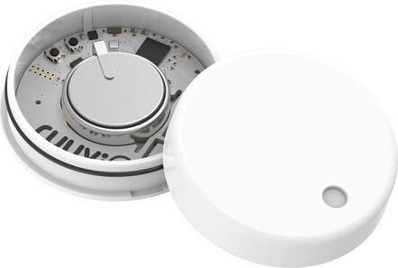
보드에 대한 자세한 정보는 RuuviTag website에서 확인할 수 있습니다.
하드웨어
RuuviTag의 물리적 특징은 다음과 같습니다.
- Nordic Semiconductor nRF52832 System-on-Chip
- STMicroelectronics LIS2DH12 accelerometer
- Bosch BME280 온도 + 상대 습도 + 기압 sensor
- NFC-A tag antenna
- 1000 mAh CR2477 battery
- button 2개
- green LED 1개
- red LED 1개
- IP67 enclosure
- long-range RF antenna
지원 기능
Zephyr 3.7.0의 이 board definition이 연결하는 interface, controller 위치, driver/component는 다음과 같습니다. on-chip은 nRF52832 내부 주변장치이고 on-board는 board에 별도로 실장된 sensor입니다.
| Interface | Controller | Driver / Component |
|---|---|---|
| ADC | on-chip | adc |
| CLOCK | on-chip | clock_control |
| FLASH | on-chip | flash |
| GPIO | on-chip | gpio |
| MPU | on-chip | arch/arm |
| NVIC | on-chip | arch/arm |
| RADIO | on-chip | Bluetooth |
| RTC | on-chip | system clock |
| SPI | on-chip | spi |
| UART | on-chip | serial |
| WDT | on-chip | watchdog |
| Humidity, Temp & Air Pressure | on-board | bme280 |
| Acc | on-board | lis2dh12 |
연결과 I/O
LED
- LED0 (red) = P0.17
- LED1 (green) = P0.19
Push button
- BUTTON0 = SW1 = P0.13
Pin 설명
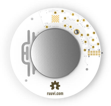
| Pin | Signal | 설명 |
|---|---|---|
| 2 | P0.29 | SPI_SCK |
| 3 | P0.28 | SPI_MISO |
| 10 | P0.04 | GPIO (GPIO / ADC pin으로 사용 가능) |
| 11 | P0.05 | GPIO (GPIO / ADC pin으로 사용 가능) |
| 12 | P0.25 | SPI_MOSI |
| 13 | P0.19 | LED2 (green) / GPIO (GPIO로 사용할 수 있지만 LED가 깜박임) |
| 14 | P0.17 | LED1 (red) / GPIO (GPIO로 사용할 수 있지만 LED가 깜박임) |
| 15 | P0.13 | Button / GPIO (GPIO로 사용 가능) |
| 16 | GND | 배터리 음극 접점 |
| 17 | Battery positive | 배터리 양극 접점 |
| 18 | Battery positive | 배터리 양극 접점 |
| 19 | SWDIO | |
| 20 | SWDCLK | |
| 21 | P0.18 | SWO / GPIO (GPIO로 사용 가능) |
| 22 | P0.21 | Reset / GPIO (device reset이 필요하지 않다면 GPIO로 사용 가능) |
| 23 | GND | 배터리 음극 접점 |
| 24 | P0.31 | GPIO (GPIO / ADC pin으로 사용 가능) |
| 25 | P0.30 | GPIO (GPIO / ADC pin으로 사용 가능) |
GPIO는 General Purpose Input Output pin을 뜻합니다.
P1: 표준 10-pin ARM Cortex debug connector (RuuviTag Rev.B1-B5)
| Pin | Signal |
|---|---|
| 1 | VDD |
| 2 | SWDIO |
| 3 | GND (배터리 음극 접점) |
| 4 | SWDCLK |
| 5 | GND (배터리 음극 접점) |
| 6 | SWO |
| 7 | No Connect |
| 8 | No Connect |
| 9 | GND (배터리 음극 접점) |
| 10 | Reset |
P1: TC2030 TagConnect (RuuviTag Rev.B6)
| Pin | Signal |
|---|---|
| 1 | Battery positive contact |
| 2 | SWDIO |
| 3 | Reset |
| 4 | SWDCLK |
| 5 | GND (배터리 음극 접점) |
| 6 | SWO |
Programming과 debugging
Flashing
일반적인 Zephyr application과 같은 방식으로 build하고 flash합니다. 자세한 절차는 공식 application build와 application 실행 문서를 참고합니다.
RuuviTag에 Zephyr를 flash하는 가장 쉬운 방법은 외부 Ruuvi DEVKIT을 사용하는 것입니다. 보드 정보는 RuuviTag DEVKIT 페이지에서 확인할 수 있습니다.
Tag를 DEVKIT에 연결하고 DEVKIT을 PC에 연결한 다음, 다음과 같이 blinky sample을 평소와 같은 방식으로 build하고 flash합니다.
west build -b ruuvi_ruuvitag samples/basic/blinky
west flash
고급 사용자는 DEVKIT 없이도 RuuviTag 뒷면의 SWDIO와 SWDCLK pin을 통해 programming할 수 있습니다.
Debugging
Ruuvi DEVKIT을 사용한다면 Nordic board를 Segger IC로 debug하는 방법을 설명하는 공식 Nordic nRF5x Segger J-Link 문서를 참고합니다.
RuuviTag LED와 button 시험
Zephyr에서 board의 button(switch)과 LED가 올바르게 작동하는지 시험할 수 있는 sample은 두 가지입니다.
예제를 build하고 flash하면 Zephyr가 board에서 올바르게 실행되는지 확인할 수 있습니다. Button과 LED 정의는 boards/ruuvi//ruuvi_ruuvitag/ruuvi_ruuvitag.dts에서 찾을 수 있습니다.
참고 자료
Source
출처
영어 원문에는 문단, 문서 지시문, 표, 코드, 코드 심벌, 경로를 그대로 보존했습니다.