Part 1
요약·해설
On-board memory 6종, communication interface 8종, 지원 controller 5종과 UART/GDB 절차를 설명합니다.
SoC
R9A07G075M24GBG · 2 MB RAM
Memory
SDRAM · NOR · Octa · HyperRAM · QSPI · EEPROM
Debug
J-Link OB · west debugserver · GDB :2331
Part 2
접을 수 있는 영어 원문 전체
영어 원문 전체 펼치기
원문 SHA-256
533F2A0BD43FCB27E3A4F016FFAF993D6F892A2502DF01879F08E40E3D9FF110
.. _rzt2m_starterkit:

Renesas Starter Kit+ for RZ/T2M
###############################

Overview
********

The Renesas Starter Kit+ for RZ/T2M is an evaluation and development kit for the RZ/T2M MPU.
The board is powered through a 5V input via a DC Power Jack or USB Type-C Connector.

.. figure:: ../../../../../../../boards/renesas/rzt2m_starterkit/doc/rzt2m_starterkit.png
   :width: 800px
   :align: center
   :alt: Starter Kit+ for RZ/T2M

   Starter Kit+ for RZ/T2M (Credit: Renesas)

Hardware
********

The board utilizes the SoC of part no. R9A07G075M24GBG, with 2MB of RAM.

It has several on-board memory components:

* SDRAM (256MBit),
* NOR Flash (256MBit),
* Octa Flash (512MBit),
* HyperRAM (512Mbit),
* QSPI Serial Flash (512Mbit),
* I2C EEPROM (32Kbit).

The communication interfaces include:

* Debug interfaces (J-Link, MIPI-10, MIPI-20),
* Ethernet,
* CAN,
* USB,
* RS485,
* UART,
* I2C,
* SPI.

Supported Features
==================

+-----------+------------+-------------------------------------+
| Interface | Controller | Driver/Component                    |
+===========+============+=====================================+
| NVIC      | on-chip    | nested vector interrupt controller  |
+-----------+------------+-------------------------------------+
| SYSTICK   | on-chip    | systick                             |
+-----------+------------+-------------------------------------+
| PINCTRL   | on-chip    | pinctrl                             |
+-----------+------------+-------------------------------------+
| UART      | on-chip    | serial                              |
+-----------+------------+-------------------------------------+
| GPIO      | on-chip    | gpio                                |
+-----------+------------+-------------------------------------+

Other hardware features are not currently supported by the port.

Connections and IOs
===================

By default, the board is configured for use with:

* UART0 connected to the USB serial port (pins K18, K19),
* UART3 connected to the PMOD Header (J25, pins H16, G20),
* LEDs defined as `led0`, `led1`, `led2` and `led3`,

The Zephyr console uses UART0.

Programming and Debugging
*************************

Debugging
=========

Connect to the board using the J-Link On-board USB connector.
Use `west` to start the debug server:

.. code-block:: console

    west debugserver

Connect GDB to the server and load an application:

.. code-block::

    target remote :2331
    file build/zephyr/zephyr.elf
    load

References
**********

.. _RZT2M Product page: https://www.renesas.com/us/en/products/microcontrollers-microprocessors/rz-mpus/rzt2m-high-performance-multi-function-mpu-realizing-high-speed-processing-and-high-precision-control
Part 3
한국어 전문 번역
개요
Renesas Starter Kit+ for RZ/T2M은 RZ/T2M MPU용 evaluation 및 development kit입니다. DC power jack 또는 USB Type-C connector를 통해 5 V input으로 전원을 공급합니다.
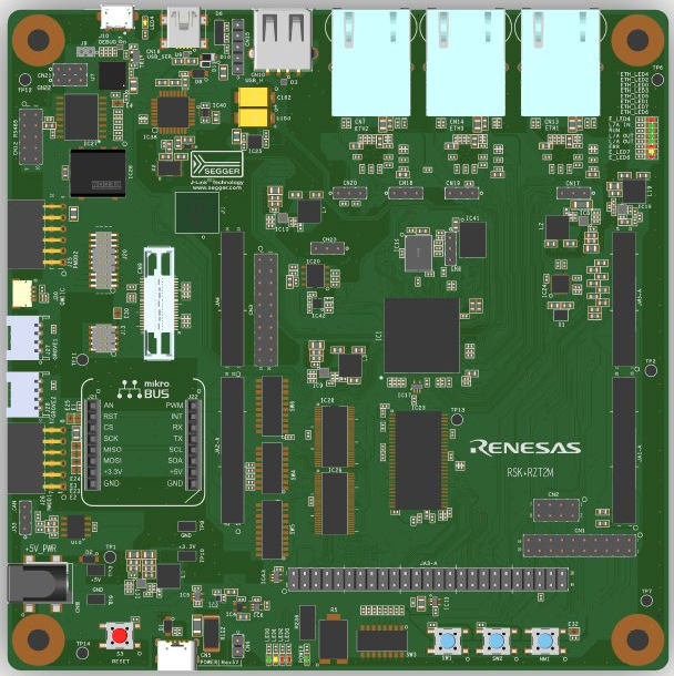
하드웨어
보드는 part number R9A07G075M24GBG SoC와 RAM 2 MB를 사용합니다.
On-board memory component는 다음과 같습니다.
- SDRAM 256 Mbit
- NOR flash 256 Mbit
- Octa flash 512 Mbit
- HyperRAM 512 Mbit
- QSPI serial flash 512 Mbit
- I2C EEPROM 32 Kbit
Communication interface는 다음과 같습니다.
- Debug interface(J-Link, MIPI-10, MIPI-20)
- Ethernet
- CAN
- USB
- RS-485
- UART
- I2C
- SPI
지원 기능
| 인터페이스 | 컨트롤러 | 드라이버/컴포넌트 |
|---|---|---|
NVIC | on-chip | nested vector interrupt controller |
SYSTICK | on-chip | systick |
PINCTRL | on-chip | pinctrl |
UART | on-chip | serial |
GPIO | on-chip | gpio |
그 밖의 hardware feature는 현재 이 port에서 지원하지 않습니다.
연결과 I/O
보드는 기본적으로 다음과 같이 구성됩니다.
- USB serial port에 연결된 UART0(pin K18, K19)
- PMOD header J25에 연결된 UART3(pin H16, G20)
- led0, led1, led2, led3으로 정의된 LED
Zephyr console은 UART0을 사용합니다.
프로그래밍과 디버깅
디버깅
J-Link On-board USB connector로 보드에 연결하고 west로 debug server를 시작합니다.
west debugserverGDB를 server에 연결하고 application을 load합니다.
target remote :2331
file build/zephyr/zephyr.elf
load
참고 자료
Source
출처
영어 원문에는 문단, 문서 지시문, 표, 코드, 코드 심벌, 경로를 그대로 보존했습니다.