Part 1
요약·해설
32 MHz/32,768 Hz clock, 지원 interface 7종, USB1 UART pin, QSPI image header와 built-in J-Link를 설명합니다.
DA1469x · Cortex-M33
Interchangeable daughterboard
QSPI · ezFlashCLI · J-Link
Part 2
접을 수 있는 영어 원문 전체
영어 원문 전체 펼치기
656AAD4CC6E8C72C92D149BB5D70DFB8E34117BF11E20F7B71BB0797ADBBAD00
.. _da1469x_dk_pro:

DA1469x Development Kit Pro
###########################

Overview
********

The DA1469x Development Kit Pro hardware provides support for the Renesas
DA1469x ARM Cortex-M33 MCU family. The development kit consist of a motherboard
with connectors and integrated debugger and an interchangeable daughterboard
with an actual MCU (e.g. DA14695 or DA14699).

.. figure:: ../../../../../../../boards/renesas/da1469x_dk_pro/doc/da14695-00hqdevkt-board.jpg
     :width: 442px
     :align: center
     :alt: DA14695 Development Kit Pro

     DA14695 Development Kit Pro (Credit: Renesas Electronics Corporation)

Hardware
********

DA1469x Development Kit Pro has two external oscillators. The frequency of
the sleep clock is 32768 Hz. The frequency of the system clock is 32 MHz.

Supported Features
==================

The _da1469x_dk_pro board configuration supports the following
hardware features:

+-----------+------------+----------------------+
| Interface | Controller | Driver/Component     |
+===========+============+======================+
| FLASH     | on-chip    | flash                |
+-----------+------------+----------------------+
| GPIO      | on-chip    | gpio                 |
+-----------+------------+----------------------+
| MPU       | on-chip    | arch/arm             |
+-----------+------------+----------------------+
| NVIC      | on-chip    | arch/arm             |
+-----------+------------+----------------------+
| RTT       | Segger     | console              |
+-----------+------------+----------------------+
| UART      | on-chip    | serial               |
+-----------+------------+----------------------+
| SPI       | on-chip    | spi                  |
+-----------+------------+----------------------+

Other hardware features, including the Configurable MAC (CMAC) controller,
are currently not supported by the port.

For more information about the DA14695 Development Kit see:

- `DA14695 DK website`_
- `DA14699 daughterboard website`_

System Clock
============

The DA1469x Development Kit Pro is configured to use the 32 MHz external oscillator
on the board.

Connections and IOs
===================

The DA1469x Development Kit Pro has one LED and one push button which can be used
by applications. The UART is connected to on-board serial converter and accessible
via USB1 port on motherboard.

The pin connections are as follows:

* LED (red), located on daughterboard = P1.01
* BUTTON, located on motherboard = P0.06
* UART RX, via USB1 on motherboard = P0.08
* UART TX, via USB1 on motherboard = P0.09

Programming and Debugging
*************************

Applications for the ``da1469x_dk_pro`` board configuration can be
built, flashed, and debugged in the usual way. See
:ref:`build_an_application` and :ref:`application_run` for more details on
building and running.

Flashing
========

The DA1469x boots from an external flash connected to QSPI interface. The image
written to flash has to have proper header prepended. The process is simplified
by using dedicated `eZFlashCLI`_ tool that takes care of writing header and can
handle different types of flash chips connected to DA1469x MCU. Follow instructions
on `ezFlashCLI`_ to install the tool. Once installed, flashing can be done in the
usual way.

.. zephyr-app-commands::
   :zephyr-app: samples/basic/blinky
   :board: da1469x_dk_pro
   :goals: build flash

Debugging
=========

The DA1469x Development Kit Pro includes a `J-Link`_ adaptor built-in on
motherboard which provides both debugging interface and serial port.
Application can be debugged in the usual way once DA1469x Development Kit Pro
is connected to PC via USB port on motherboard.

References
**********

.. target-notes::

.. _DA14695 DK website: https://www.renesas.com/eu/en/products/interface-connectivity/wireless-communications/bluetooth-low-energy/da14695-00hqdevkt-p-smartbond-da14695-bluetooth-low-energy-52-development-kit-pro
.. _DA14699 daughterboard website: https://www.renesas.com/br/en/products/interface-connectivity/wireless-communications/bluetooth-low-energy/da14699-00hrdb-p-smartbond-da14695-bluetooth-low-energy-52-development-kit-pro-vfbga100-daughterboard
.. _DA1469x Datasheet: https://www.renesas.com/eu/en/document/dst/da1469x-datasheet
.. _J-Link: https://www.segger.com/jlink-debug-probes.html
.. _ezFlashCLI: https://github.com/ezflash/ezFlashCLI/
Part 3
한국어 전문 번역
개요
DA1469x Development Kit Pro hardware는 Renesas DA1469x ARM Cortex-M33 MCU family를 지원합니다. Kit는 connector와 integrated debugger가 있는 motherboard, 실제 MCU(예: DA14695 또는 DA14699)를 탑재한 교체식 daughterboard로 구성됩니다.
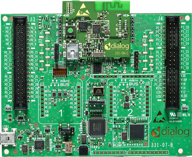
하드웨어
DA1469x Development Kit Pro에는 외부 oscillator가 2개 있습니다. Sleep clock 주파수는 32,768 Hz이고 system clock 주파수는 32 MHz입니다.
지원 기능
da1469x_dk_pro board configuration은 다음 hardware feature를 지원합니다.
| 인터페이스 | 컨트롤러 | 드라이버/컴포넌트 |
|---|---|---|
FLASH | on-chip | flash |
GPIO | on-chip | gpio |
MPU | on-chip | arch/arm |
NVIC | on-chip | arch/arm |
RTT | Segger | console |
UART | on-chip | serial |
SPI | on-chip | spi |
Configurable MAC(CMAC) controller를 포함한 그 밖의 hardware feature는 현재 이 port에서 지원하지 않습니다.
자세한 정보는 DA14695 DK website와 DA14699 daughterboard website에서 확인할 수 있습니다.
System clock
DA1469x Development Kit Pro은 보드의 32 MHz 외부 oscillator를 사용하도록 구성됩니다.
연결과 I/O
DA1469x Development Kit Pro에는 application에서 사용할 수 있는 LED 1개와 push button 1개가 있습니다. UART는 on-board serial converter에 연결되며 motherboard의 USB1 port를 통해 접근할 수 있습니다.
Pin 연결은 다음과 같습니다.
- Daughterboard의 LED(red) = P1.01
- Motherboard의 BUTTON = P0.06
- Motherboard USB1을 통한 UART RX = P0.08
- Motherboard USB1을 통한 UART TX = P0.09
프로그래밍과 디버깅
da1469x_dk_pro board configuration용 application은 일반적인 방법으로 build, flash, debug할 수 있습니다.
플래시
DA1469x는 QSPI interface에 연결된 외부 flash에서 boot합니다. Flash에 쓰는 image 앞에는 올바른 header가 붙어야 합니다. 전용 ezFlashCLI tool은 header를 작성하고 DA1469x MCU에 연결된 여러 flash chip type을 처리하여 이 과정을 단순화합니다. Repository 지침에 따라 tool을 설치하면 일반적인 방법으로 flash할 수 있습니다.
west build -b da1469x_dk_pro samples/basic/blinky
west flash
디버깅
DA1469x Development Kit Pro motherboard에는 debug interface와 serial port를 모두 제공하는 built-in J-Link adapter가 있습니다. Motherboard USB port로 kit를 PC에 연결하면 평소와 같이 application을 debug할 수 있습니다.
참고 자료
Source
출처
영어 원문에는 문단, 문서 지시문, 표, 코드, 코드 심벌, 경로를 그대로 보존했습니다.