Part 1
요약·해설
Quectel BG96와 sensor 4종, 지원 interface 14종, LED pin, J-Link 기반 build·flash·debug 절차를 설명합니다.
nRF52840 · Cortex-M4F
BG96 · LTE Cat M1/NB1 · GNSS
SHTC3 · OPT3001 · LPS22HB · LIS3DH
Part 2
접을 수 있는 영어 원문 전체
영어 원문 전체 펼치기
8047BEC1E15D60D858CE0E4F3BB69742104FE9E3DEE6B3974C3E5AE2BE1F4D29
.. _rak5010_nrf52840:

RAK5010
#######

Overview
********

WisTrio NB-IoT Tracker Pro (RAK5010) is a tracker
with integrated LTE CAT M1 & NB1, GPS, BLE, and sensors.
It is built on the Quectel BG96 LTE CAT M1 & NB1 module,
which has an integrated GPS receiver. The MCU running
the board is a Nordic nRF52840 controller.

As it has both GPS and BLE it can be used for outdoor
and indoor scenarios, where location-based services need be present.

The built-in sensors for RAK5010 are temperature and
humidity sensor, motion sensor, pressure sensor, and light sensor.
The extension IOs allow adding more sensors in addition to the on-board ones.

This board is particularly suitable to be used as a
quick testing and prototyping tool for applications
requiring NB-IoT connectivity. Application development
supports the GCC environment.

.. image:: ../../../../../../../boards/rak/rak5010/doc/img/rak5010-front-parts.jpg
     :align: center
     :alt: RAK5010-NRF52840

Hardware
********

- nRF52840 ARM Cortex-M4F Processor
- 32.768 kHz crystal oscillator
- 1 Micro-AB USB OTG host/device
- Quectel BG96, with LTE CAT M1, LTE NB1, and GNSS
- iPEX connectors for the LTE and GPS antenna and an on-board ceramic antenna for the BLE.
- nano-SIM and ESIM options.
- Multiple interfaces, I2C, UART, GPIO, ADC
- 1 user LED
- 1 SHTC3 Humidity and Temperature Sensor
- 1 OPT3001DNPR Ambient Light Sensor
- 1 LPS22HB Pressure Sensor
- 1 LIS3DH Motion Sensor
- Powered by either Micro USB, 3.7V rechargeable battery or a 5V Solar Panel Port

Supported Features
==================

The ``rak5010/nrf52840`` board configuration supports the following hardware features:

+-----------+------------+----------------------+
| Interface | Controller | Driver/Component     |
+===========+============+======================+
| ADC       | on-chip    | adc                  |
+-----------+------------+----------------------+
| CLOCK     | on-chip    | clock_control        |
+-----------+------------+----------------------+
| FLASH     | on-chip    | flash                |
+-----------+------------+----------------------+
| GPIO      | on-chip    | gpio                 |
+-----------+------------+----------------------+
| I2C(M)    | on-chip    | i2c                  |
+-----------+------------+----------------------+
| MPU       | on-chip    | arch/arm             |
+-----------+------------+----------------------+
| NVIC      | on-chip    | arch/arm             |
+-----------+------------+----------------------+
| PWM       | on-chip    | pwm                  |
+-----------+------------+----------------------+
| RADIO     | on-chip    | Bluetooth,           |
|           |            | ieee802154           |
+-----------+------------+----------------------+
| RTC       | on-chip    | system clock         |
+-----------+------------+----------------------+
| SPI(M/S)  | on-chip    | spi                  |
+-----------+------------+----------------------+
| UART      | on-chip    | serial               |
+-----------+------------+----------------------+
| USB       | on-chip    | usb                  |
+-----------+------------+----------------------+
| WDT       | on-chip    | watchdog             |
+-----------+------------+----------------------+

Other hardware features have not been enabled yet for this board.

Connections and IOs
===================

LED
---

* LED0 (green) = P0.12


Programming and Debugging
*************************

The RAK5010 board shall be connected to a Segger Embedded Debugger Unit
`J-Link OB <https://www.segger.com/jlink-ob.html>`_.  This provides a debug
interface to the NRF52840 chip. You can use JLink to communicate with
the NRF52840.

Flashing
========

#. Download JLink from the Segger `JLink Downloads Page`_.  Go to the section
   "J-Link Software and Documentation Pack" and install the "J-Link Software
   and Documentation pack for Linux".  The application JLinkExe needs to be
   accessible from your path.

#. Run your favorite terminal program to listen for output.  Under Linux the
   terminal should be :code:`/dev/ttyACM0`. For example:

   .. code-block:: console

      $ minicom -D /dev/ttyACM0 -o

   The -o option tells minicom not to send the modem initialization string.
   Connection should be configured as follows:

   - Speed: 115200
   - Data: 8 bits
   - Parity: None
   - Stop bits: 1

#. Connect the RAK5010 board to your host computer using the USB debug port.
   Then build and flash the :ref:`hello_world` application.

   .. zephyr-app-commands::
      :zephyr-app: samples/hello_world
      :board: rak5010/nrf52840
      :goals: build flash

   You should see "Hello World! rak5010_nrf52840" in your terminal.

Debugging
=========

You can debug an application in the usual way.  Here is an example for the
:ref:`hello_world` application.

.. zephyr-app-commands::
   :zephyr-app: samples/hello_world
   :board: rak5010/nrf52840
   :maybe-skip-config:
   :goals: debug

References
**********

.. target-notes::

.. _RAK5010 Product Description:
    https://doc.rakwireless.com/datasheet/rakproducts/rak5010-wistrio-nb-iot-tracker-datasheet

.. _JLink Downloads Page:
    https://www.segger.com/downloads/jlink
Part 3
한국어 전문 번역
개요
WisTrio NB-IoT Tracker Pro(RAK5010)는 LTE CAT M1과 NB1, GPS, BLE, sensor를 통합한 tracker입니다. GPS receiver가 내장된 Quectel BG96 LTE CAT M1/NB1 module을 기반으로 하며, Nordic nRF52840 controller가 보드를 구동합니다.
GPS와 BLE를 모두 갖추어 위치 기반 service가 필요한 실외 및 실내 환경에서 사용할 수 있습니다. 내장 sensor에는 온습도 sensor, motion sensor, pressure sensor, light sensor가 있으며, extension I/O로 on-board sensor 외의 sensor를 더 연결할 수 있습니다.
이 보드는 NB-IoT 연결이 필요한 application을 빠르게 시험하고 prototype으로 만들 때 특히 적합합니다. Application development는 GCC environment를 지원합니다.
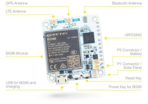
하드웨어
- nRF52840 ARM Cortex-M4F processor
- 32.768 kHz crystal oscillator
- Micro-AB USB OTG host/device 1개
- LTE CAT M1, LTE NB1, GNSS를 지원하는 Quectel BG96
- LTE와 GPS antenna용 iPEX connector, BLE용 on-board ceramic antenna
- Nano-SIM 및 eSIM option
- I2C, UART, GPIO, ADC를 포함한 여러 interface
- User LED 1개
SHTC3humidity/temperature sensor 1개OPT3001DNPRambient light sensor 1개LPS22HBpressure sensor 1개LIS3DHmotion sensor 1개- Micro USB, 3.7 V rechargeable battery 또는 5 V solar panel port 전원
지원 기능
rak5010/nrf52840 board configuration은 다음 hardware feature를 지원합니다.
| 인터페이스 | 컨트롤러 | 드라이버/컴포넌트 |
|---|---|---|
ADC | on-chip | adc |
CLOCK | on-chip | clock_control |
FLASH | on-chip | flash |
GPIO | on-chip | gpio |
I2C(M) | on-chip | i2c |
MPU | on-chip | arch/arm |
NVIC | on-chip | arch/arm |
PWM | on-chip | pwm |
RADIO | on-chip | Bluetooth, ieee802154 |
RTC | on-chip | system clock |
SPI(M/S) | on-chip | spi |
UART | on-chip | serial |
USB | on-chip | usb |
WDT | on-chip | watchdog |
그 밖의 hardware feature는 아직 이 보드에서 활성화되지 않았습니다.
연결과 I/O
LED
- LED0(green) =
P0.12
프로그래밍과 디버깅
RAK5010 board는 Segger Embedded Debugger Unit인 J-Link OB에 연결해야 합니다. 이 장치는 nRF52840 chip용 debug interface를 제공하며, J-Link로 nRF52840과 통신할 수 있습니다.
플래시
- SEGGER J-Link download page에서 J-Link를 내려받습니다. “J-Link Software and Documentation Pack” section으로 이동해 Linux용 pack을 설치하고,
JLinkExeapplication이PATH에서 실행되는지 확인합니다. - 원하는 terminal program으로 출력을 수신합니다. Linux에서는 terminal이
/dev/ttyACM0여야 합니다. 예:
$ minicom -D /dev/ttyACM0 -o-o option은 minicom이 modem initialization string을 보내지 않도록 합니다. 연결은 속도 115200, data 8 bits, parity None, stop bits 1로 설정합니다.
- USB debug port로 RAK5010 board를 host computer에 연결한 다음
hello_worldapplication을 build하고 flash합니다.
west build -b rak5010/nrf52840 samples/hello_world
west flash
Terminal에 Hello World! rak5010_nrf52840가 표시되어야 합니다.
디버깅
Application은 일반적인 방법으로 debug할 수 있습니다. 다음은 hello_world application 예시입니다.
west build -b rak5010/nrf52840 samples/hello_world
west debug
참고 자료
Source
출처
영어 원문에는 문단, 문서 지시문, 표, 코드, 코드 심벌, 경로를 그대로 보존했습니다.