Part 1
요약·해설
지원 기능 9종, J3·PMOD pin, boot 방식, sysbuild output과 Espressif OpenOCD 설치를 설명합니다.
ESP32-C3-MINI-1
iCE40UP5K-SG48
Simple · MCUboot/sysbuild
Part 2
접을 수 있는 영어 원문 전체
영어 원문 전체 펼치기
EA3081F0F8C24052412D10A88A1640192E6311032469A520110069EA2097C85C
.. _icev_wireless:

ICE-V Wireless
##############

Overview
********

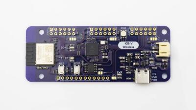
The ICE-V Wireless is a combined ESP32C3 and iCE40 FPGA board.

See the `ICE-V Wireless Github Project`_ for details.

.. figure:: ../../../../../../../boards/others/icev_wireless/doc/img/icev_wireless.jpg
   :align: center
   :alt: ICE-V Wireless

   ICE-V Wireless

Hardware
********

This board combines an Espressif ESP32-C3-MINI-1 (which includes 4MB of flash in the module) with a
Lattice iCE40UP5k-SG48 FPGA to allow WiFi and Bluetooth control of the FPGA. ESP32 and FPGA I/O is
mostly uncommitted except for the pins used for SPI communication between ESP32 and FPGA. Several
of the ESP32C3 GPIO pins are available for additonal interfaces such as serial, ADC, I2C, etc.

For details on ESP32-C3 hardware please refer to the following resources:

* `ESP32-C3-MINI-1 Datasheet`_
* `ESP32-C3 Datasheet`_
* `ESP32-C3 Technical Reference Manual`_

For details on iCE40 hardware please refer to the following resources:

* `iCE40 UltraPlus Family Datasheet`_

Supported Features
==================

The ICE-V Wireless board configuration supports the following hardware
features:

+-----------+------------+------------------+
| Interface | Controller | Driver/Component |
+===========+============+==================+
| PMP       | on-chip    | arch/riscv       |
+-----------+------------+------------------+
| INTMTRX   | on-chip    | intc_esp32c3     |
+-----------+------------+------------------+
| PINMUX    | on-chip    | pinctrl_esp32    |
+-----------+------------+------------------+
| USB UART  | on-chip    | serial_esp32_usb |
+-----------+------------+------------------+
| GPIO      | on-chip    | gpio_esp32       |
+-----------+------------+------------------+
| UART      | on-chip    | uart_esp32       |
+-----------+------------+------------------+
| I2C       | on-chip    | i2c_esp32        |
+-----------+------------+------------------+
| SPI       | on-chip    | spi_esp32_spim   |
+-----------+------------+------------------+
| ADC       | on-chip    |                  |
+-----------+------------+------------------+

Other hardware features have not been enabled yet for this board.

Connections and IOs
===================

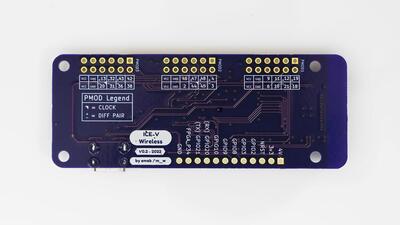
The ICE-V Wireless provides 1 row of reference, ESP32-C3, and iCE40 signals
brought out to J3, as well as 3 PMOD connectors for interfacing directly to
the iCE40 FPGA. Note that several of the iCE40 pins brought out to the PMOD
connectors are capable of operating as differential pairs.

.. figure:: ../../../../../../../boards/others/icev_wireless/doc/img/icev_wireless_back.jpg
   :align: center
   :alt: ICE-V Wireless (Back)

   ICE-V Wireless (Back)

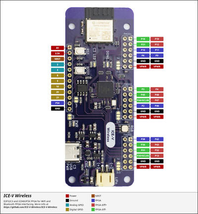
The J3 pins are 4V, 3.3V, NRST, GPIO2, GPIO3, GPIO8, GPIO9, GPIO10, GPIO20,
GPIO21, FPGA_P34, and GND. Note that GPIO2 and GPIO3 may be configured for
ADC operation.

For PMOD details, please refer to the `PMOD Specification`_ and the image
below.

.. figure:: ../../../../../../../boards/others/icev_wireless/doc/img/icev_wireless_pinout.jpg
   :align: center
   :alt: ICE-V Wireless Pinout

Programming and Debugging
*************************

Programming and debugging for the ICE-V Wireless ESP32-C3 target is
incredibly easy 🎉 following the steps below.

Building and Flashing
*********************

Simple boot
===========

The board could be loaded using the single binary image, without 2nd stage bootloader.
It is the default option when building the application without additional configuration.

.. note::

   Simple boot does not provide any security features nor OTA updates.

MCUboot bootloader
==================

User may choose to use MCUboot bootloader instead. In that case the bootloader
must be build (and flash) at least once.

There are two options to be used when building an application:

1. Sysbuild
2. Manual build

.. note::

   User can select the MCUboot bootloader by adding the following line
   to the board default configuration file.

   .. code:: cfg

      CONFIG_BOOTLOADER_MCUBOOT=y

Sysbuild
========

The sysbuild makes possible to build and flash all necessary images needed to
bootstrap the board with the ESP32 SoC.

To build the sample application using sysbuild use the command:

.. zephyr-app-commands::
   :tool: west
   :app: samples/hello_world
   :board: icev_wireless
   :goals: build
   :west-args: --sysbuild
   :compact:

By default, the ESP32 sysbuild creates bootloader (MCUboot) and application
images. But it can be configured to create other kind of images.

Build directory structure created by sysbuild is different from traditional
Zephyr build. Output is structured by the domain subdirectories:

.. code-block::

  build/
  ├── hello_world
  │   └── zephyr
  │       ├── zephyr.elf
  │       └── zephyr.bin
  ├── mcuboot
  │    └── zephyr
  │       ├── zephyr.elf
  │       └── zephyr.bin
  └── domains.yaml

.. note::

   With ``--sysbuild`` option the bootloader will be re-build and re-flash
   every time the pristine build is used.

For more information about the system build please read the :ref:`sysbuild` documentation.

Manual build
============

During the development cycle, it is intended to build & flash as quickly possible.
For that reason, images can be build one at a time using traditional build.

The instructions following are relevant for both manual build and sysbuild.
The only difference is the structure of the build directory.

.. note::

   Remember that bootloader (MCUboot) needs to be flash at least once.

For the :code:`Hello, world!` application, follow the instructions below.

.. zephyr-app-commands::
   :zephyr-app: samples/hello_world
   :board: icev_wireless
   :goals: build flash

Open the serial monitor using the following command:

.. code-block:: console

   $ west espressif monitor

After the board has automatically reset and booted, you should see the following
message in the monitor:

.. code-block:: console

   ***** Booting Zephyr OS vx.x.x-xxx-gxxxxxxxxxxxx *****
   Hello World! icev_wireless

Debugging
*********

As with much custom hardware, the ESP32C3 modules require patches to
OpenOCD that are not upstreamed. Espressif maintains their own fork of
the project. The custom OpenOCD can be obtained by running the following extension:

.. code-block:: console

   west espressif install

.. note::

   By default, the OpenOCD will be downloaded and installed under $HOME/.espressif/tools/zephyr directory
   (%USERPROFILE%/.espressif/tools/zephyr on Windows).

The Zephyr SDK uses a bundled version of OpenOCD by default. You can overwrite that behavior by adding the
``-DOPENOCD=<path/to/bin/openocd> -DOPENOCD_DEFAULT_PATH=<path/to/openocd/share/openocd/scripts>``
parameter when building.

Here is an example for building the :ref:`hello_world` application.

.. zephyr-app-commands::
   :zephyr-app: samples/hello_world
   :board: icev_wireless
   :goals: build flash
   :gen-args: -DOPENOCD=<path/to/bin/openocd> -DOPENOCD_DEFAULT_PATH=<path/to/openocd/share/openocd/scripts>

You can debug an application in the usual way. Here is an example for the
:ref:`hello_world` application.

.. zephyr-app-commands::
   :zephyr-app: samples/hello_world
   :board: icev_wireless
   :maybe-skip-config:
   :goals: debug

References
**********

.. _ICE-V Wireless Github Project:
   https://github.com/ICE-V-Wireless/ICE-V-Wireless

.. _ESP32-C3-MINI-1 Datasheet:
   https://www.espressif.com/sites/default/files/documentation/esp32-c3-mini-1_datasheet_en.pdf

.. _ESP32-C3 Datasheet:
   https://www.espressif.com/sites/default/files/documentation/esp32-c3_datasheet_en.pdf

.. _ESP32-C3 Technical Reference Manual:
   https://www.espressif.com/sites/default/files/documentation/esp32-c3_technical_reference_manual_en.pdf

.. _iCE40 UltraPlus Family Datasheet:
   https://www.latticesemi.com/-/media/LatticeSemi/Documents/DataSheets/iCE/iCE40-UltraPlus-Family-Data-Sheet.ashx

.. _PMOD Specification:
   https://digilent.com/reference/_media/reference/pmod/pmod-interface-specification-1_2_0.pdf
Part 3
한국어 전문 번역
개요
ICE-V Wireless는 ESP32-C3와 iCE40 FPGA를 결합한 board입니다.
하드웨어
4 MB module flash가 있는 Espressif ESP32-C3-MINI-1과 Lattice iCE40UP5K-SG48 FPGA를 결합해 Wi-Fi와 Bluetooth로 FPGA를 제어할 수 있습니다. ESP32-FPGA SPI 통신 pin을 제외하면 두 device I/O 대부분은 용도가 고정되지 않았고, 일부 ESP32-C3 GPIO는 serial, ADC, I2C 등에 쓸 수 있습니다.
ESP32-C3-MINI-1 datasheet, ESP32-C3 datasheet/TRM과 iCE40 UltraPlus family datasheet를 참고하십시오.
지원 기능
| 인터페이스 | 컨트롤러 | 드라이버/컴포넌트 |
|---|---|---|
PMP | on-chip | arch/riscv |
INTMTRX | on-chip | intc_esp32c3 |
PINMUX | on-chip | pinctrl_esp32 |
USB UART | on-chip | serial_esp32_usb |
GPIO | on-chip | gpio_esp32 |
UART | on-chip | uart_esp32 |
I2C | on-chip | i2c_esp32 |
SPI | on-chip | spi_esp32_spim |
ADC | on-chip | |
표 밖의 기능은 아직 활성화되지 않았습니다.
연결과 I/O
J3에는 reference, ESP32-C3, iCE40 signal 한 행이 나오며 iCE40 FPGA 직접 연결용 PMOD connector 3개가 있습니다. PMOD로 나온 일부 iCE40 pin은 differential pair로 동작할 수 있습니다.
J3 pin은 4V, 3.3V, NRST, GPIO2, GPIO3, GPIO8, GPIO9, GPIO10, GPIO20, GPIO21, FPGA_P34, GND입니다. GPIO2와 GPIO3은 ADC로 설정할 수 있습니다.
Build와 flash
Simple boot
Second-stage bootloader 없이 single binary image를 load하며 추가 설정 없는 기본값입니다.
MCUboot
MCUboot를 선택하면 적어도 한 번 bootloader를 build·flash해야 합니다. Application은 sysbuild 또는 manual build로 만들 수 있습니다.
CONFIG_BOOTLOADER_MCUBOOT=ySysbuild
ESP32 SoC bootstrap에 필요한 image를 함께 build·flash합니다.
# Zephyr 저장소 루트에서
west build --sysbuild -b icev_wireless samples/hello_world
기본값은 MCUboot와 application image이며 다른 image도 구성할 수 있습니다. Domain별 output 구조는 다음과 같습니다.
build/
├── hello_world
│   └── zephyr
│       ├── zephyr.elf
│       └── zephyr.bin
├── mcuboot
│   └── zephyr
│       ├── zephyr.elf
│       └── zephyr.bin
└── domains.yaml--sysbuild에서 pristine build를 할 때마다 bootloader를 다시 build·flash합니다.
Manual build
개발 중 빠른 반복을 위해 image를 하나씩 traditional build할 수 있습니다. 이후 지침은 build directory 구조만 다르고 sysbuild에도 적용됩니다. MCUboot는 최소 한 번 flash되어 있어야 합니다.
# Zephyr 저장소 루트에서
west build -b icev_wireless samples/hello_world
west flash
Serial monitor:
$ west espressif monitor자동 reset·boot 후 출력:
***** Booting Zephyr OS vx.x.x-xxx-gxxxxxxxxxxxx *****
Hello World! icev_wireless
Debug
ESP32-C3 module은 upstream에 없는 OpenOCD patch가 필요하며 Espressif가 fork를 유지합니다. Extension으로 custom OpenOCD를 설치합니다.
west espressif install기본 설치 경로는 Linux/macOS $HOME/.espressif/tools/zephyr, Windows %USERPROFILE%/.espressif/tools/zephyr입니다. Zephyr SDK bundled OpenOCD 대신 custom binary/script를 지정할 수 있습니다.
# Zephyr 저장소 루트에서
west build -b icev_wireless samples/hello_world -- -DOPENOCD=<path/to/bin/openocd> -DOPENOCD_DEFAULT_PATH=<path/to/openocd/share/openocd/scripts>
west flash
일반 debug
# Zephyr 저장소 루트에서
west build -b icev_wireless samples/hello_world
west debug
참고 자료
Source
출처
영어 원문에는 문단, 문서 지시문, 표, 코드, 코드 심벌, 경로를 그대로 보존했습니다.