Part 1
요약·해설
지원 기능 8종, connector 34행, 8 MHz HSE 기반 168 MHz clock과 serial output을 보존했습니다.
MCU
STM32F405RG · Cortex-M4
Features
USB · watchdog · RTC · RNG
Debug
ST-Link V2 · external JTAG
Part 2
접을 수 있는 영어 원문 전체
영어 원문 전체 펼치기
원문 SHA-256
1A480603DF3D83B12DC08CD6FE69FF3B600916D1E17D5BC4AA61F5FBE6B36564
.. _olimex_stm32_h405:

OLIMEX-STM32-H405
#################

Overview
********

The OLIMEX-STM32-H405 board is based on the STMicroelectronics STM32F405RG ARM
Cortex-M4 CPU.

.. figure:: ../../../../../../../boards/olimex/stm32_h405/doc/olimex_stm32_h405_top.jpg
     :align: center
     :alt: OLIMEX-STM32-H405

     OLIMEX-STM32-H405 top

.. figure:: ../../../../../../../boards/olimex/stm32_h405/doc/olimex_stm32_h405_bottom.jpg
     :align: center
     :alt: OLIMEX-STM32-H405

     OLIMEX-STM32-H405 bottom

Hardware
********

Information about the board can be found at the
`OLIMEX-STM32-H405 website`_ and `OLIMEX-STM32-H405 user manual`_.
The `ST STM32F405RG Datasheet`_ contains the processor's
information and the datasheet.

Supported Features
==================

The olimex_stm32_h405 board configuration supports the following
hardware features:

+-----------+------------+-------------------------+
| Interface | Controller | Driver/Component        |
+===========+============+=========================+
| NVIC      | on-chip    | nested vectored         |
|           |            | interrupt controller    |
+-----------+------------+-------------------------+
| SYSTICK   | on-chip    | system clock            |
+-----------+------------+-------------------------+
| UART      | on-chip    | serial port             |
+-----------+------------+-------------------------+
| GPIO      | on-chip    | gpio                    |
+-----------+------------+-------------------------+
| USB       | on-chip    | USB device              |
+-----------+------------+-------------------------+
| WATCHDOG  | on-chip    | independent watchdog    |
+-----------+------------+-------------------------+
| COUNTER   | on-chip    | rtc                     |
+-----------+------------+-------------------------+
| RNG       | on-chip    | random number generator |
+-----------+------------+-------------------------+

Other hardware features have not been enabled yet for this board.


Pin Mapping
===========

LED
---

* USER_LED (green) = PC12
* PWR_LED (red) = power

Push buttons
------------

* USER_BUTTON = PA0
* RST = NRST

External Connectors
-------------------

JTAG debug

+-------+--------------+-------+--------------+
| PIN # | Signal Name  | Pin # | Signal Name  |
+=======+==============+=======+==============+
| 1     | +3.3V        | 2     | +3.3V        |
+-------+--------------+-------+--------------+
| 3     | PB4 / TRST   | 4     | GND          |
+-------+--------------+-------+--------------+
| 5     | PA15 / TDI   | 6     | GND          |
+-------+--------------+-------+--------------+
| 7     | PA13 / TMS   | 8     | GND          |
+-------+--------------+-------+--------------+
| 9     | PA14 / TCK   | 10    | GND          |
+-------+--------------+-------+--------------+
| 11    | GND          | 12    | GND          |
+-------+--------------+-------+--------------+
| 13    | PB3 / TDO    | 14    | GND          |
+-------+--------------+-------+--------------+
| 15    | GND          | 16    | GND          |
+-------+--------------+-------+--------------+
| 17    | RST          | 18    | GND          |
+-------+--------------+-------+--------------+
| 19    | GND          | 20    | GND          |
+-------+--------------+-------+--------------+

USB Type B

+-------+------------------+
| PIN # | Signal Name      |
+=======+==================+
| 1     | +5V_USB          |
+-------+------------------+
| 2     | PA11 / USBDM     |
+-------+------------------+
| 3     | PA12 / USBDP     |
+-------+------------------+
| 4     | GND              |
+-------+------------------+

EXT1 header

+-------+------------------+-------+------------------+
| PIN # | Signal Name      | Pin # | Signal Name      |
+=======+==================+=======+==================+
| 1     |                  | 2     |                  |
+-------+------------------+-------+------------------+
| ...   | ...              | ...   | ...              |
+-------+------------------+-------+------------------+
| 9     | PC11 (USB DISC)  | 10    | PC12 (LED)       |
+-------+------------------+-------+------------------+
| ...   | ...              | ...   | ...              |
+-------+------------------+-------+------------------+
| 25    |                  | 26    |                  |
+-------+------------------+-------+------------------+

EXT2 header

+-------+------------------+-------+------------------+
| PIN # | Signal Name      | Pin # | Signal Name      |
+=======+==================+=======+==================+
| 1     |                  | 2     |                  |
+-------+------------------+-------+------------------+
| ...   | ...              | ...   | ...              |
+-------+------------------+-------+------------------+
| 5     |                  | 6     | GND              |
+-------+------------------+-------+------------------+
| 7     | PA2 / USART2_TX  | 8     |                  |
+-------+------------------+-------+------------------+
| 9     |                  | 10    | PA3 / USART2_RX  |
+-------+------------------+-------+------------------+
| ...   | ...              | ...   | ...              |
+-------+------------------+-------+------------------+
| 25    |                  | 26    |                  |
+-------+------------------+-------+------------------+


System Clock
============

OLIMEX-STM32-H405 has two external oscillators. The frequency of
the slow clock is 32.768 kHz. The frequency of the main clock
is 8 MHz. The processor can setup HSE to drive the master clock,
which can be set as high as 168 MHz.

Programming and Debugging
*************************
The OLIMEX-STM32-H405 board does not include an embedded debug tool
interface. You will need to use ST tools or an external JTAG probe.
In the following examples a ST-Link V2 USB dongle is used.

Flashing an application to the Olimex-STM32-H405
================================================

The sample application :ref:`hello_world` is being used in this tutorial.

Connect the ST-Link USB dongle to your host computer and to the JTAG port of
the OLIMEX-STM32-H405 board.

Now build and flash the application.

.. zephyr-app-commands::
   :zephyr-app: samples/hello_world
   :board: olimex_stm32_h405
   :goals: build flash

Run a serial host program to connect with your board:

.. code-block:: console

   $ minicom -D /dev/ttyACM0

After resetting the board, you should see the following message:

.. code-block:: console

   *** Booting Zephyr OS build v2.7.99-3008-g2341052abe7c  ***
   Hello World! olimex_stm32_h405


Debugging
=========

You can debug an application in the usual way. Here is an example for the
:ref:`hello_world` application.

.. zephyr-app-commands::
   :zephyr-app: samples/hello_world
   :board: olimex_stm32_h405
   :maybe-skip-config:
   :goals: debug

.. _OLIMEX-STM32-H405 website:
   https://www.olimex.com/Products/ARM/ST/STM32-H405/

.. _OLIMEX-STM32-H405 user manual:
   https://www.olimex.com/Products/ARM/ST/STM32-H405/resources/STM32-H405_UM.pdf

.. _ST STM32F405RG Datasheet:
   https://www.st.com/resource/en/reference_manual/dm00031020.pdf
Part 3
한국어 전문 번역
개요
OLIMEX-STM32-H405는 STMicroelectronics STM32F405RG ARM Cortex-M4 CPU 기반 보드입니다.
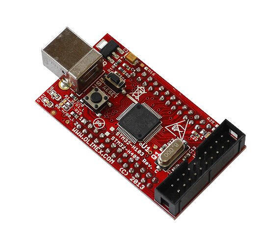
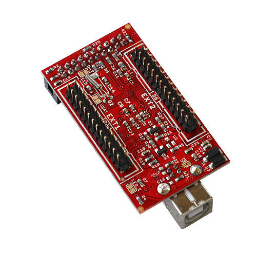
보드 정보는 website와 user manual, processor 정보는 ST STM32F405RG datasheet에서 확인할 수 있습니다.
지원 기능
| 인터페이스 | 컨트롤러 | 드라이버/컴포넌트 |
|---|---|---|
NVIC | on-chip | nested vectored interrupt controller |
SYSTICK | on-chip | system clock |
UART | on-chip | serial port |
GPIO | on-chip | gpio |
USB | on-chip | USB device |
WATCHDOG | on-chip | independent watchdog |
COUNTER | on-chip | rtc |
RNG | on-chip | random number generator |
표에 없는 하드웨어 기능은 아직 활성화되지 않았습니다.
핀 배치
LED와 button
- USER_LED (green):
PC12 - PWR_LED (red): power
- USER_BUTTON:
PA0 - RST:
NRST
JTAG debug
| PIN # | Signal Name | Pin # | Signal Name |
|---|---|---|---|
1 | +3.3V | 2 | +3.3V |
3 | PB4 / TRST | 4 | GND |
5 | PA15 / TDI | 6 | GND |
7 | PA13 / TMS | 8 | GND |
9 | PA14 / TCK | 10 | GND |
11 | GND | 12 | GND |
13 | PB3 / TDO | 14 | GND |
15 | GND | 16 | GND |
17 | RST | 18 | GND |
19 | GND | 20 | GND |
USB Type B
| PIN # | Signal Name |
|---|---|
1 | +5V_USB |
2 | PA11 / USBDM |
3 | PA12 / USBDP |
4 | GND |
EXT1 header
| PIN # | Signal Name | Pin # | Signal Name |
|---|---|---|---|
1 | | 2 | |
... | ... | ... | ... |
9 | PC11 (USB DISC) | 10 | PC12 (LED) |
... | ... | ... | ... |
25 | | 26 | |
EXT2 header
| PIN # | Signal Name | Pin # | Signal Name |
|---|---|---|---|
1 | | 2 | |
... | ... | ... | ... |
5 | | 6 | GND |
7 | PA2 / USART2_TX | 8 | |
9 | | 10 | PA3 / USART2_RX |
... | ... | ... | ... |
25 | | 26 | |
System clock
외부 oscillator는 slow clock 32.768 kHz와 main clock 8 MHz 두 개입니다. Processor는 HSE를 master clock source로 설정해 최대 168 MHz로 동작할 수 있습니다.
프로그래밍과 디버깅
Embedded debug interface가 없어 ST 도구나 외부 JTAG probe가 필요합니다. 아래 예는 ST-Link V2 USB dongle과 hello_world를 사용합니다.
Application flash
ST-Link를 host와 board JTAG port에 연결한 뒤 build하고 flash합니다.
# Zephyr 저장소 루트에서
west build -b olimex_stm32_h405 samples/hello_world
west flash
Serial host program으로 연결합니다.
$ minicom -D /dev/ttyACM0Reset 후 다음 메시지가 보입니다.
*** Booting Zephyr OS build v2.7.99-3008-g2341052abe7c  ***
Hello World! olimex_stm32_h405
Debug
# Zephyr 저장소 루트에서
west build -b olimex_stm32_h405 samples/hello_world
west debug
참고 자료
Source
출처
영어 원문에는 문단, 문서 지시문, 표, 코드, 코드 심벌, 경로를 그대로 보존했습니다.