Part 1
요약·해설
지원 기능 10종, GPIO/PWM LED mapping, console pin, 80 MHz RUN mode와 TRACE32 load·erase·verify option을 설명합니다.
Dual CAN FD PHY · daisy chain
S32K146 · Cortex-M4F · 80 MHz RUN
J-Link 기본 · TRACE32 선택
Part 2
접을 수 있는 영어 원문 전체
영어 원문 전체 펼치기
7EAE7AAB415196CB0212E919ED141133D16E73583BB2208E373370D1BA0189E6
.. _ucans32k1sic:

NXP UCANS32K1SIC
################

Overview
********

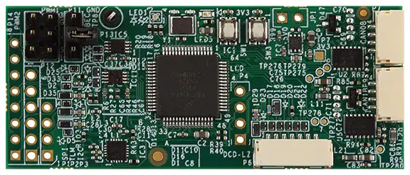
`NXP UCANS32K1SIC`_ is a CAN signal improvement capability (SIC) evaluation
board designed for both automotive and industrial applications. The UCANS32K1SIC
provides two CAN SIC interfaces and is based on the 32-bit Arm Cortex-M4F
`NXP S32K146`_ microcontroller.

.. image:: ../../../../../../../boards/nxp/ucans32k1sic/doc/img/ucans32k1sic_top.webp
     :align: center
     :alt: NXP UCANS32K1SIC (TOP)

Hardware
********

- NXP S32K146
    - Arm Cortex-M4F @ up to 112 Mhz
    - 1 MB Flash
    - 128 KB SRAM
    - up to 127 I/Os
    - 3x FlexCAN with 2x FD
    - eDMA, 12-bit ADC, MPU, ECC and more.

- Interfaces:
    - DCD-LZ debug interface with SWD + Console / UART
    - Dual CAN FD PHYs with dual connectors for daisy chain operation
    - JST-GH DroneCode compliant standard connectors and I/O headers
    - user RGB LED and button.

More information about the hardware and design resources can be found at
`NXP UCANS32K1SIC`_ website.

Supported Features
==================

The ``ucans32k1sic`` board configuration supports the following hardware features:

============  ==========  ================================
Interface     Controller  Driver/Component
============  ==========  ================================
SYSMPU        on-chip     mpu
PORT          on-chip     pinctrl
GPIO          on-chip     gpio
LPUART        on-chip     serial
LPI2C         on-chip     i2c
LPSPI         on-chip     spi
FTM           on-chip     pwm
FlexCAN       on-chip     can
Watchdog      on-chip     watchdog
RTC           on-chip     counter
============  ==========  ================================

The default configuration can be found in the Kconfig file
:zephyr_file:`boards/nxp/ucans32k1sic/ucans32k1sic_defconfig`.

Connections and IOs
===================

This board has 5 GPIO ports named from ``gpioa`` to ``gpioe``.

Pin control can be further configured from your application overlay by adding
children nodes with the desired pinmux configuration to the singleton node
``pinctrl``. Supported properties are described in
:zephyr_file:`dts/bindings/pinctrl/nxp,kinetis-pinctrl.yaml`.

LEDs
----

The UCANS32K1SIC board has one user RGB LED that can be used either as a GPIO
LED or as a PWM LED.

.. table:: RGB LED as GPIO LED
   :widths: auto

   ===============  ================  ===============  =====
   Devicetree node  Devicetree alias  Label            Pin
   ===============  ================  ===============  =====
   led1_red         led0              LED1_RGB_RED     PTD15
   led1_green       led1              LED1_RGB_GREEN   PTD16
   led1_blue        led2              LED1_RGB_BLUE    PTD0
   ===============  ================  ===============  =====

.. table:: RGB LED as PWM LED
   :widths: auto

   ===============  ========================  ==================  ================
   Devicetree node  Devicetree alias          Label               Pin
   ===============  ========================  ==================  ================
   led1_red_pwm     pwm-led0 / red-pwm-led    LED1_RGB_RED_PWM    PTD15 / FTM0_CH0
   led1_green_pwm   pwm-led1 / green-pwm-led  LED1_RGB_GREEN_PWM  PTD16 / FTM0_CH1
   led1_blue_pwm    pwm-led2 / blue-pwm-led   LED1_RGB_BLUE_PWM   PTD0 / FTM0_CH2
   ===============  ========================  ==================  ================

The user can control the LEDs in any way. An output of ``0`` illuminates the LED.

Buttons
-------

The UCANS32K1SIC board has one user button:

=======================  ==============  =====
Devicetree node          Label           Pin
=======================  ==============  =====
sw0 / button_3           SW3             PTD15
=======================  ==============  =====

Serial Console
==============

The serial console is provided via ``lpuart1`` on the 7-pin DCD-LZ debug
connector ``P6``.

=========  =====  ============
Connector  Pin    Pin Function
=========  =====  ============
P6.2       PTC7   LPUART1_TX
P6.3       PTC6   LPUART1_RX
=========  =====  ============

System Clock
============

The Arm Cortex-M4F core is configured to run at 80 MHz (RUN mode).

Programming and Debugging
*************************

Applications for the ``ucans32k1sic`` board can be built in the usual way as
documented in :ref:`build_an_application`.

This board configuration supports `Lauterbach TRACE32`_ and `SEGGER J-Link`_
West runners for flashing and debugging applications. Follow the steps described
in :ref:`lauterbach-trace32-debug-host-tools` and :ref:`jlink-debug-host-tools`,
to setup the flash and debug host tools for these runners, respectively. The
default runner is J-Link.

Flashing
========

Run the ``west flash`` command to flash the application using SEGGER J-Link.
Alternatively, run ``west flash -r trace32`` to use Lauterbach TRACE32.

The Lauterbach TRACE32 runner supports additional options that can be passed
through command line:

.. code-block:: console

   west flash -r trace32 --startup-args elfFile=<elf_path> loadTo=<flash/sram>
      eraseFlash=<yes/no> verifyFlash=<yes/no>

Where:

- ``<elf_path>`` is the path to the Zephyr application ELF in the output
  directory
- ``loadTo=flash`` loads the application to the SoC internal program flash
  (:kconfig:option:`CONFIG_XIP` must be set), and ``loadTo=sram`` load the
  application to SRAM. The default is ``flash``.
- ``eraseFlash=yes`` erases the whole content of SoC internal flash before the
  application is downloaded to either Flash or SRAM. This routine takes time to
  execute. The default is ``no``.
- ``verifyFlash=yes`` verify the SoC internal flash content after programming
  (use together with ``loadTo=flash``). The default is ``no``.

For example, to erase and verify flash content:

.. code-block:: console

   west flash -r trace32 --startup-args elfFile=build/zephyr/zephyr.elf loadTo=flash eraseFlash=yes verifyFlash=yes

Debugging
=========

Run the ``west debug`` command to start a GDB session using SEGGER J-Link.
Alternatively, run ``west debug -r trace32`` to launch the Lauterbach TRACE32
software debugging interface.

References
**********

.. target-notes::

.. _NXP UCANS32K1SIC:
   https://www.nxp.com/design/development-boards/analog-toolbox/can-sic-evaluation-board:UCANS32K1SIC

.. _NXP S32K146:
   https://www.nxp.com/products/processors-and-microcontrollers/s32-automotive-platform/s32k-auto-general-purpose-mcus/s32k1-microcontrollers-for-automotive-general-purpose:S32K1

.. _Lauterbach TRACE32:
   https://www.lauterbach.com

.. _SEGGER J-Link:
   https://wiki.segger.com/S32Kxxx
Part 3
한국어 전문 번역
개요
NXP UCANS32K1SIC는 차량 및 산업 application용 CAN signal improvement capability(SIC) 평가 보드입니다. CAN SIC interface 2개를 제공하며 32-bit Arm Cortex-M4F 기반 NXP S32K146 MCU를 사용합니다.
하드웨어
- NXP S32K146: 최대 112 MHz Arm Cortex-M4F
- 1 MB flash와 128 KB SRAM
- 최대 127 I/O
- FlexCAN 3개, 그중 FD 2개
- eDMA, 12-bit ADC, MPU, ECC
- SWD와 console/UART를 제공하는 DCD-LZ debug interface
- Daisy-chain용 dual connector를 갖춘 dual CAN FD PHY
- DroneCode 호환 JST-GH standard connector와 I/O header
- User RGB LED와 button
지원 기능
| 인터페이스 | 컨트롤러 | 드라이버/컴포넌트 |
|---|---|---|
SYSMPU | on-chip | mpu |
PORT | on-chip | pinctrl |
GPIO | on-chip | gpio |
LPUART | on-chip | serial |
LPI2C | on-chip | i2c |
LPSPI | on-chip | spi |
FTM | on-chip | pwm |
FlexCAN | on-chip | can |
Watchdog | on-chip | watchdog |
RTC | on-chip | counter |
기본 구성은 boards/nxp/ucans32k1sic/ucans32k1sic_defconfig에 있습니다.
연결과 I/O
보드에는 gpioa부터 gpioe까지 GPIO port 5개가 있습니다. Application overlay에서 singleton pinctrl node 아래에 원하는 pinmux child node를 추가해 pin control을 더 구성할 수 있습니다. 지원 property는 dts/bindings/pinctrl/nxp,kinetis-pinctrl.yaml에 정의됩니다.
RGB LED를 GPIO LED로 사용
| Devicetree node | Devicetree alias | Label | Pin |
|---|---|---|---|
led1_red | led0 | LED1_RGB_RED | PTD15 |
led1_green | led1 | LED1_RGB_GREEN | PTD16 |
led1_blue | led2 | LED1_RGB_BLUE | PTD0 |
RGB LED를 PWM LED로 사용
| Devicetree node | Devicetree alias | Label | Pin |
|---|---|---|---|
led1_red_pwm | pwm-led0 / red-pwm-led | LED1_RGB_RED_PWM | PTD15 / FTM0_CH0 |
led1_green_pwm | pwm-led1 / green-pwm-led | LED1_RGB_GREEN_PWM | PTD16 / FTM0_CH1 |
led1_blue_pwm | pwm-led2 / blue-pwm-led | LED1_RGB_BLUE_PWM | PTD0 / FTM0_CH2 |
LED는 자유롭게 제어할 수 있으며 output 0이 LED를 켭니다.
버튼
| Devicetree node | Label | Pin |
|---|---|---|
sw0 / button_3 | SW3 | PTD15 |
직렬 콘솔
Serial console은 7-pin DCD-LZ debug connector P6의 lpuart1로 제공됩니다.
| Connector | Pin | Pin Function |
|---|---|---|
P6.2 | PTC7 | LPUART1_TX |
P6.3 | PTC6 | LPUART1_RX |
시스템 클록
Arm Cortex-M4F core는 RUN mode에서 80 MHz로 동작하도록 구성됩니다.
프로그래밍과 디버깅
ucans32k1sic application은 일반 방식으로 build합니다. Lauterbach TRACE32와 SEGGER J-Link West runner를 지원하며 기본 runner는 J-Link입니다.
플래시
west flash는 SEGGER J-Link를 사용합니다. TRACE32는 west flash -r trace32로 선택합니다. TRACE32 runner에는 다음 추가 option을 전달할 수 있습니다.
west flash -r trace32 --startup-args elfFile=<elf_path> loadTo=<flash/sram>
eraseFlash=<yes/no> verifyFlash=<yes/no><elf_path>: output directory의 Zephyr application ELF 경로loadTo=flash: SoC 내부 program flash에 load하며CONFIG_XIP가 필요합니다.loadTo=sram은 SRAM에 load합니다. 기본값은flash입니다.eraseFlash=yes: Flash 또는 SRAM에 download하기 전에 내부 flash 전체를 지웁니다. 시간이 걸리며 기본값은no입니다.verifyFlash=yes: programming 뒤 내부 flash 내용을 검증합니다.loadTo=flash와 함께 사용하며 기본값은no입니다.
Flash 전체를 지우고 기록 결과를 검증하는 예입니다.
west flash -r trace32 --startup-args elfFile=build/zephyr/zephyr.elf loadTo=flash eraseFlash=yes verifyFlash=yes디버깅
west debug는 SEGGER J-Link로 GDB session을 시작합니다. Lauterbach TRACE32는 west debug -r trace32를 사용합니다.
참고 자료
Source
출처
영어 원문에는 문단, 문서 지시문, 표, 코드, 코드 심벌, 경로를 그대로 보존했습니다.