Part 1
요약·해설
기능 18종·핀 15행, core별 boot/memory map, OCRAM2 16 KB 제약, M4→M7 flash 순서, probe와 boot switch 절차를 설명합니다.
Cortex-M7 600 MHz · Cortex-M4 240 MHz
OCRAM2 512 KB · usable 16 KB
OpenAMP sysbuild · M4 first
Part 2
접을 수 있는 영어 원문 전체
영어 원문 전체 펼치기
C6BFC32F185B7DFEEA5A55EFDF0266FFCF957FF2B1DACC13617A74BBE50581CB
.. _mimxrt1160_evk:

NXP MIMXRT1160-EVK
##################

Overview
********

The dual core i.MX RT1160 runs on the Cortex-M7 core at 600 MHz and on the
Cortex-M4 at 240 MHz. The i.MX RT1160 MCU offers support over a wide
temperature range and is qualified for consumer, industrial and automotive
markets.

.. image:: ../../../../../../../boards/nxp/mimxrt1160_evk/doc/mimxrt1160_evk.jpg
   :align: center
   :alt: MIMXRT1160-EVK

Hardware
********

- MIMXRT1166DVM6A MCU

  - 600MHz Cortex-M7 & 240Mhz Cortex-M4
  - 2MB SRAM with 512KB of TCM for Cortex-M7 and 256KB of TCM for Cortex-M4

- Memory

  - 512 Mbit SDRAM
  - 128 Mbit QSPI Flash
  - 512 Mbit Octal Flash
  - TF socket for SD card

- Display

  - MIPI LCD connector

- Ethernet

  - 10/100 Mbit/s Ethernet PHY
  - 10/100/1000 Mbit/s Ethernet PHY

- USB

  - USB 2.0 OTG connector
  - USB 2.0 host connector

- Audio

  - 3.5 mm audio stereo headphone jack
  - Board-mounted microphone
  - Left and right speaker out connectors

- Power

  - 5 V DC jack

- Debug

  - JTAG 20-pin connector
  - OpenSDA with DAPLink

- Sensor

  - MIPI camera sensor connector

- Expansion port

  - Arduino interface

- CAN bus connector

For more information about the MIMXRT1160 SoC and MIMXRT1160-EVK board, see
these references:

- `i.MX RT1160 Website`_
- `i.MX RT1160 Datasheet`_
- `i.MX RT1160 Reference Manual`_
- `MIMXRT1160-EVK Website`_
- `MIMXRT1160-EVK Board Hardware User's Guide`_

External Memory
===============

This platform has the following external memories:

+--------------------+------------+-------------------------------------+
| Device             | Controller | Status                              |
+====================+============+=====================================+
| W9825G6KH          | SEMC       | Enabled via device configuration    |
|                    |            | data block, which sets up SEMC at   |
|                    |            | boot time                           |
+--------------------+------------+-------------------------------------+
| IS25WP128          | FLEXSPI    | Enabled via flash configurationn    |
|                    |            | block, which sets up FLEXSPI at     |
|                    |            | boot time.                          |
+--------------------+------------+-------------------------------------+

Supported Features
==================

The mimxrt1160_evk board configuration supports the hardware features listed
below.  For additional features not yet supported, please also refer to the
:ref:`mimxrt1170_evk` , which is the superset board in NXP's i.MX RT11xx family.
NXP prioritizes enabling the superset board with NXP's Full Platform Support for
Zephyr.  Therefore, the mimxrt1170_evk board may have additional features
already supported, which can also be re-used on this mimxrt1160_evk board:

+-----------+------------+-------------------------------------+
| Interface | Controller | Driver/Component                    |
+===========+============+=====================================+
| NVIC      | on-chip    | nested vector interrupt controller  |
+-----------+------------+-------------------------------------+
| SYSTICK   | on-chip    | systick                             |
+-----------+------------+-------------------------------------+
| GPIO      | on-chip    | gpio                                |
+-----------+------------+-------------------------------------+
| COUNTER   | on-chip    | counter                             |
+-----------+------------+-------------------------------------+
| UART      | on-chip    | serial port-polling;                |
|           |            | serial port-interrupt               |
+-----------+------------+-------------------------------------+
| SPI       | on-chip    | spi                                 |
+-----------+------------+-------------------------------------+
| I2C       | on-chip    | i2c                                 |
+-----------+------------+-------------------------------------+
| ADC       | on-chip    | adc                                 |
+-----------+------------+-------------------------------------+
| CAN       | on-chip    | flexcan                             |
+-----------+------------+-------------------------------------+
| WATCHDOG  | on-chip    | watchdog                            |
+-----------+------------+-------------------------------------+
| PWM       | on-chip    | pwm                                 |
+-----------+------------+-------------------------------------+
| DMA       | on-chip    | dma                                 |
+-----------+------------+-------------------------------------+
| GPT       | on-chip    | gpt                                 |
+-----------+------------+-------------------------------------+
| USB       | on-chip    | USB Device                          |
+-----------+------------+-------------------------------------+
| HWINFO    | on-chip    | Unique device serial number         |
+-----------+------------+-------------------------------------+
| CAAM RNG  | on-chip    | entropy                             |
+-----------+------------+-------------------------------------+
| FLEXSPI   | on-chip    | flash programming                   |
+-----------+------------+-------------------------------------+
| PIT       | on-chip    | pit                                 |
+-----------+------------+-------------------------------------+

The default configuration can be found in the defconfig file:
:zephyr_file:`boards/nxp/mimxrt1160_evk/mimxrt1160_evk_mimxrt1166_cm7_defconfig`

Other hardware features are not currently supported by the port.


Connections and I/Os
====================

The MIMXRT1160 SoC has six pairs of pinmux/gpio controllers.

+---------------+-----------------+---------------------------+
| Name          | Function        | Usage                     |
+===============+=================+===========================+
| WAKEUP        | GPIO            | SW7                       |
+---------------+-----------------+---------------------------+
| GPIO_AD_04    | GPIO            | LED                       |
+---------------+-----------------+---------------------------+
| GPIO_AD_24    | LPUART1_TX      | UART Console              |
+---------------+-----------------+---------------------------+
| GPIO_AD_25    | LPUART1_RX      | UART Console              |
+---------------+-----------------+---------------------------+
| GPIO_LPSR_00  | CAN3_TX         | flexcan                   |
+---------------+-----------------+---------------------------+
| GPIO_LPSR_01  | CAN3_RX         | flexcan                   |
+---------------+-----------------+---------------------------+
| GPIO_AD_29    | SPI1_CS0        | spi                       |
+---------------+-----------------+---------------------------+
| GPIO_AD_28    | SPI1_CLK        | spi                       |
+---------------+-----------------+---------------------------+
| GPIO_AD_30    | SPI1_SDO        | spi                       |
+---------------+-----------------+---------------------------+
| GPIO_AD_31    | SPI1_SDI        | spi                       |
+---------------+-----------------+---------------------------+
| GPIO_AD_08    | LPI2C1_SCL      | i2c                       |
+---------------+-----------------+---------------------------+
| GPIO_AD_09    | LPI2C1_SDA      | i2c                       |
+---------------+-----------------+---------------------------+
| GPIO_LPSR_05  | LPI2C5_SCL      | i2c                       |
+---------------+-----------------+---------------------------+
| GPIO_LPSR_04  | LPI2C5_SDA      | i2c                       |
+---------------+-----------------+---------------------------+
| GPIO_AD_04    | FLEXPWM1_PWM2   | pwm                       |
+---------------+-----------------+---------------------------+


Dual Core samples
*****************

+-----------+------------------+----------------------------+
| Core      | Boot Address     | Comment                    |
+===========+==================+============================+
| Cortex M7 | 0x30000000[630K] | primary core               |
+-----------+------------------+----------------------------+
| Cortex M4 | 0x20020000[96k]  | boots from OCRAM           |
+-----------+------------------+----------------------------+

+----------+------------------+-----------------------+
| Memory   | Address[Size]    | Comment               |
+==========+==================+=======================+
| flexspi1 | 0x30000000[16M]  | Cortex M7 flash       |
+----------+------------------+-----------------------+
| sdram0   | 0x80030000[64M]  | Cortex M7 ram         |
+----------+------------------+-----------------------+
| ocram    | 0x20020000[512K] | Cortex M4 "flash"     |
+----------+------------------+-----------------------+
| sram1    | 0x20000000[128K] | Cortex M4 ram         |
+----------+------------------+-----------------------+
| ocram2   | 0x200C0000[512K] | Mailbox/shared memory |
+----------+------------------+-----------------------+

Only the first 16K of ocram2 has the correct MPU region attributes set to be
used as shared memory

System Clock
============

The MIMXRT1160 SoC is configured to use SysTick as the system clock source,
running at 600MHz. When targeting the M4 core, SysTick will also be used,
running at 240MHz

When power management is enabled, the 32 KHz low frequency
oscillator on the board will be used as a source for the GPT timer to
generate a system clock. This clock enables lower power states, at the
cost of reduced resolution

Serial Port
===========

The MIMXRT1160 SoC has 12 UARTs. One is configured for the console and the
remaining are not used.

Programming and Debugging
*************************

Build and flash applications as usual (see :ref:`build_an_application` and
:ref:`application_run` for more details).

Building a Dual-Core Image
==========================
Dual core samples load the M4 core image from flash into the shared ``ocram``
region. The M7 core then sets the M4 boot address to this region. The only
sample currently enabled for dual core builds is the ``openamp`` sample.
To flash a dual core sample, the M4 image must be flashed first, so that it is
written to flash. Then, the M7 image must be flashed. The openamp sysbuild
sample will do this automatically by setting the image order.

The secondary core can be debugged normally in single core builds
(where the target is ``mimxrt1160_evk/mimxrt1166/cm4``). For dual core builds, the
secondary core should be placed into a loop, then a debugger can be attached
(see `AN13264`_, section 4.2.3 for more information)

Configuring a Debug Probe
=========================

A debug probe is used for both flashing and debugging the board. This board is
configured by default to use the :ref:`opensda-daplink-onboard-debug-probe`,
however the :ref:`pyocd-debug-host-tools` do not yet support programming the
external flashes on this board so you must reconfigure the board for one of the
following debug probes instead.

Using J-Link
------------

Install the :ref:`jlink-debug-host-tools` and make sure they are in your search
path.

There are two options: the onboard debug circuit can be updated with Segger
J-Link firmware, or :ref:`jlink-external-debug-probe` can be attached to the
EVK. See `Using J-Link with MIMXRT1160-EVK or MIMXRT1170-EVK`_ for more details.

Using LinkServer
----------------

Install the :ref:`linkserver-debug-host-tools` and make sure they are in your
search path.  LinkServer works with the CMSIS-DAP firmware include in LinkServer
install. Please follow the ``LPCScrypt\docs\Debug_Probe_Firmware_Programming.pdf``
for more details.

Linkserver is the default runner. You may also se the ``-r linkserver`` option
with West to use the LinkServer runner.

Configuring a Console
=====================

Regardless of your choice in debug probe, we will use the OpenSDA
microcontroller as a usb-to-serial adapter for the serial console. Check that
jumpers J5 and J8 are **on** (they are on by default when boards ship from
the factory) to connect UART signals to the OpenSDA microcontroller.

Connect a USB cable from your PC to J11.

Use the following settings with your serial terminal of choice (minicom, putty,
etc.):

- Speed: 115200
- Data: 8 bits
- Parity: None
- Stop bits: 1

Flashing
========

Here is an example for the :ref:`hello_world` application.

Before power on the board, make sure SW1 is set to 0001b

.. zephyr-app-commands::
   :zephyr-app: samples/hello_world
   :board: mimxrt1160_evk/mimxrt1166/cm7
   :goals: flash

Power off the board, and change SW1 to 0010b. Then power on the board and
open a serial terminal, reset the board (press the SW4 button), and you should
see the following message in the terminal:

.. code-block:: console

   ***** Booting Zephyr OS v2.6.0-xxxx-xxxxxxxxxxxxx *****
   Hello World! mimxrt1160_evk

Debugging
=========

Here is an example for the :ref:`hello_world` application.

.. zephyr-app-commands::
   :zephyr-app: samples/hello_world
   :board: mimxrt1160_evk/mimxrt1166/cm7
   :goals: debug

Open a serial terminal, step through the application in your debugger, and you
should see the following message in the terminal:

.. code-block:: console

   ***** Booting Zephyr OS v2.4.0-xxxx-xxxxxxxxxxxxx *****
   Hello World! mimxrt1160_evk

.. _MIMXRT1160-EVK Website:
   https://www.nxp.com/design/development-boards/i-mx-evaluation-and-development-boards/i-mx-rt1160-evaluation-kit:MIMXRT1160-EVK

.. _MIMXRT1160-EVK Board Hardware User's Guide:
   https://www.nxp.com/webapp/Download?colCode=UM11617

.. _i.MX RT1160 Website:
   https://www.nxp.com/products/processors-and-microcontrollers/arm-microcontrollers/i-mx-rt-crossover-mcus/i-mx-rt1160-crossover-mcu-family-high-performance-mcu-with-arm-cortex-m7-and-cortex-m4-cores:i.MX-RT1160

.. _i.MX RT1160 Datasheet:
   https://www.nxp.com/docs/en/data-sheet/IMXRT1160CEC.pdf

.. _i.MX RT1160 Reference Manual:
   https://www.nxp.com/webapp/Download?colCode=IMXRT1160RM

.. _Using J-Link with MIMXRT1160-EVK or MIMXRT1170-EVK:
   https://community.nxp.com/t5/i-MX-RT-Knowledge-Base/Using-J-Link-with-MIMXRT1160-EVK-or-MIMXRT1170-EVK/ta-p/1529760

.. _AN13264:
   https://www.nxp.com/docs/en/application-note/AN13264.pdf
Part 3
한국어 전문 번역
개요
Dual-core i.MX RT1160은 Cortex-M7을 600 MHz, Cortex-M4를 240 MHz로 실행합니다. 넓은 온도 범위를 지원하고 consumer, industrial, automotive 시장용으로 인증되었습니다.
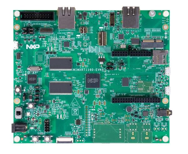
하드웨어
MIMXRT1166DVM6A: 600 MHz Cortex-M7, 240 MHz Cortex-M4- 2 MB SRAM: M7용 512 KB TCM, M4용 256 KB TCM
- 512 Mbit SDRAM, 128 Mbit QSPI Flash, 512 Mbit Octal Flash, SD용 TF socket
- MIPI LCD와 MIPI camera sensor connector
- 10/100 및 10/100/1000 Mbit/s Ethernet PHY
- USB 2.0 OTG·host, stereo audio와 speaker output
- 5 V DC, JTAG 20-pin, DAPLink OpenSDA
- Arduino expansion과 CAN bus connector
외부 메모리
| 장치 | 컨트롤러 | 상태 |
|---|---|---|
W9825G6KH | SEMC | 부팅 시 SEMC를 설정하는 device configuration data block으로 활성화 |
IS25WP128 | FLEXSPI | 부팅 시 FLEXSPI를 설정하는 flash configuration block으로 활성화 |
지원 기능
mimxrt1160_evk 구성은 다음 기능을 지원합니다. 추가 기능은 i.MX RT11xx 상위 집합 보드 mimxrt1170_evk에 우선 활성화된 NXP Full Platform Support에서 재사용할 수 있습니다.
| 인터페이스 | 컨트롤러 | 드라이버/컴포넌트 |
|---|---|---|
NVIC | on-chip | nested vector interrupt controller |
SYSTICK | on-chip | systick |
GPIO | on-chip | gpio |
COUNTER | on-chip | counter |
UART | on-chip | serial port-polling; serial port-interrupt |
SPI | on-chip | spi |
I2C | on-chip | i2c |
ADC | on-chip | adc |
CAN | on-chip | flexcan |
WATCHDOG | on-chip | watchdog |
PWM | on-chip | pwm |
DMA | on-chip | dma |
GPT | on-chip | gpt |
USB | on-chip | USB Device |
HWINFO | on-chip | Unique device serial number |
CAAM RNG | on-chip | entropy |
FLEXSPI | on-chip | flash programming |
PIT | on-chip | pit |
기본 CM7 구성은 boards/nxp/mimxrt1160_evk/mimxrt1160_evk_mimxrt1166_cm7_defconfig에 있습니다. 표 밖의 기능은 현재 port에서 지원하지 않습니다.
연결과 I/O
SoC에는 pinmux/GPIO controller 쌍이 6개 있습니다.
| 이름 | 기능 | 용도 |
|---|---|---|
WAKEUP | GPIO | SW7 |
GPIO_AD_04 | GPIO | LED |
GPIO_AD_24 | LPUART1_TX | UART Console |
GPIO_AD_25 | LPUART1_RX | UART Console |
GPIO_LPSR_00 | CAN3_TX | flexcan |
GPIO_LPSR_01 | CAN3_RX | flexcan |
GPIO_AD_29 | SPI1_CS0 | spi |
GPIO_AD_28 | SPI1_CLK | spi |
GPIO_AD_30 | SPI1_SDO | spi |
GPIO_AD_31 | SPI1_SDI | spi |
GPIO_AD_08 | LPI2C1_SCL | i2c |
GPIO_AD_09 | LPI2C1_SDA | i2c |
GPIO_LPSR_05 | LPI2C5_SCL | i2c |
GPIO_LPSR_04 | LPI2C5_SDA | i2c |
GPIO_AD_04 | FLEXPWM1_PWM2 | pwm |
Dual-core sample
| 코어 | 부트 주소 | 설명 |
|---|---|---|
Cortex M7 | 0x30000000[630K] | primary core |
Cortex M4 | 0x20020000[96k] | OCRAM에서 부팅 |
| 메모리 | 주소[크기] | 설명 |
|---|---|---|
flexspi1 | 0x30000000[16M] | Cortex M7 flash |
sdram0 | 0x80030000[64M] | Cortex M7 RAM |
ocram | 0x20020000[512K] | Cortex M4 "flash" |
sram1 | 0x20000000[128K] | Cortex M4 RAM |
ocram2 | 0x200C0000[512K] | mailbox/shared memory |
ocram2 중 올바른 MPU region attribute가 설정되어 shared memory로 사용할 수 있는 영역은 앞 16 KB뿐입니다.
시스템 클록과 직렬 포트
M7 target에서는 SysTick이 600 MHz, M4 target에서는 240 MHz로 동작합니다. 전원 관리 시 32 KHz oscillator를 GPT timer source로 사용해 해상도를 낮추는 대신 저전력 상태를 지원합니다. UART 12개 중 하나만 console로 구성합니다.
프로그래밍과 디버깅
Dual-core image 빌드
Dual-core sample은 M4 image를 flash에서 shared ocram 영역으로 load하고, M7이 M4 boot address를 그 영역으로 설정합니다. 현재 dual-core build가 활성화된 sample은 openamp뿐입니다.
- M4 image가 flash에 기록되도록 먼저 flash합니다.
- 그다음 M7 image를 flash합니다.
- OpenAMP sysbuild sample은 image 순서를 설정해 이 작업을 자동으로 수행합니다.
Single-core build의 secondary target mimxrt1160_evk/mimxrt1166/cm4는 일반 방식으로 debug할 수 있습니다. Dual-core build에서는 secondary core를 loop에 둔 뒤 debugger를 attach합니다. 자세한 내용은 AN13264 4.2.3절을 참고하십시오.
디버그 프로브
기본 probe는 OpenSDA DAPLink지만 pyOCD는 이 보드의 external flash programming을 지원하지 않으므로 J-Link 또는 LinkServer로 재구성해야 합니다.
J-Link
J-Link host tool을 설치한 뒤 온보드 circuit을 SEGGER J-Link firmware로 갱신하거나 외부 J-Link를 EVK에 연결합니다.
LinkServer
LinkServer를 설치하고 검색 경로에 넣습니다. 설치본에 포함된 CMSIS-DAP firmware를 사용하며 LPCScrypt/docs/Debug_Probe_Firmware_Programming.pdf 절차를 따릅니다. LinkServer가 기본 runner이며 명시하려면 West에 -r linkserver를 사용합니다.
콘솔
OpenSDA를 USB-to-serial adapter로 사용합니다. J5/J8이 장착되어 있는지 확인하고 PC를 J11에 연결합니다. Terminal은 115200 baud, 8 bits, parity None, stop bit 1입니다.
플래시
전원을 켜기 전에 SW1을 0001b로 설정합니다.
# Zephyr 저장소 루트에서
west build -b mimxrt1160_evk/mimxrt1166/cm7 samples/hello_world
west flash
보드 전원을 끄고 SW1을 0010b로 바꾼 뒤 다시 켭니다. SW4로 reset하면 다음 메시지가 표시됩니다.
***** Booting Zephyr OS v2.6.0-xxxx-xxxxxxxxxxxxx *****
Hello World! mimxrt1160_evk
디버깅
# Zephyr 저장소 루트에서
west build -b mimxrt1160_evk/mimxrt1166/cm7 samples/hello_world
west debug
단계 실행 중 terminal 출력은 다음과 같습니다.
***** Booting Zephyr OS v2.4.0-xxxx-xxxxxxxxxxxxx *****
Hello World! mimxrt1160_evk
참고 자료
Source
출처
영어 원문에는 문단, 문서 지시문, 표, 코드, 코드 심벌, 경로를 그대로 보존했습니다.