Part 1
요약·해설
보드 메모리와 확장 인터페이스, IOCON 핀 배치, pyOCD에서 지원되지 않는 LPC-Link2 CMSIS-DAP를 J-Link로 재구성하는 이유와 flash/debug 절차를 설명합니다.
LPC51U68 · 150 MHz
256 KB flash · 96 KB SRAM
LPC-Link2 · J-Link firmware
Part 2
접을 수 있는 영어 원문 전체
영어 원문 전체 펼치기
5F68D7BD56CC5848AD823FB0A4C9F8E1F056BECC23745A7616EBE25541E9A83E
.. _lpcxpresso51u68:

NXP LPCXPRESSO51U68
###################

Overview
********

The LPCXpresso51u68 development board uses an NXP LPC51U68 MCU based
on an ARM CORTEX-M0+ core.

.. figure:: ../../../../../../../boards/nxp/lpcxpresso51u68/doc/lpcxpresso51u68.jpg
   :align: center
   :alt: LPCXpresso51U68

Hardware
********

- LPC51U68 M0+ running at up to 150 MHz
- Memory

  - 256KB of flash memory
  - 96KB of SRAM
- On-board high-speed USB based debug probe with CMSIS-DAP and J-Link protocol
  support, can debug the on-board LPC51U68 or an external target
- External debug probe option
- Tri-color LED, target reset, ISP & interrupt/user buttons for easy testing of
  software functionality
- Expansion options based on Arduino UNO and PMOD™, plus additional expansion
  port pins
- FTDI UART Connector

More information can be found here:

- `LPC51U68 SoC Website`_
- `LPC51U68 Datasheet`_

Supported Features
==================

The lpcxpresso51u68 support the following features:

+-----------+------------+-------------------------------------+
| Interface | Controller | Driver/Component                    |
+===========+============+=====================================+
| NVIC      | on-chip    | nested vector interrupt controller  |
+-----------+------------+-------------------------------------+
| SYSTICK   | on-chip    | systick                             |
+-----------+------------+-------------------------------------+
| IOCON     | on-chip    | pinmux                              |
+-----------+------------+-------------------------------------+
| CLOCK     | on-chip    | clock and reset control             |
+-----------+------------+-------------------------------------+
| GPIO      | on-chip    | gpio                                |
+-----------+------------+-------------------------------------+
| I2C       | on-chip    | i2c master/slave controller         |
+-----------+------------+-------------------------------------+
| UART      | on-chip    | serial port-polling;                |
|           |            | serial port interrupt               |
+-----------+------------+-------------------------------------+
| SPI       | on-chip    | SPI master                          |
+-----------+------------+-------------------------------------+

Other hardware is not yet supported on Zephyr.

Connections and IOs
===================

The IOCON controller can be used to configure the LPC51U68 pins.

+---------+-----------------+----------------------------+
| Name    | Function        | Usage                      |
+=========+=================+============================+
| PIO0_0  | UART            | USART RX                   |
+---------+-----------------+----------------------------+
| PIO0_1  | UART            | USART TX                   |
+---------+-----------------+----------------------------+
| PIO1_10 | GPIO            | GREEN LED                  |
+---------+-----------------+----------------------------+
| PIO0_29 | GPIO            | RED LED                    |
+---------+-----------------+----------------------------+
| PIO1_9  | GPIO            | BLUE_LED                   |
+---------+-----------------+----------------------------+
| PIO0_25 | I2C             | I2C SCL                    |
+---------+-----------------+----------------------------+
| PIO0_26 | I2C             | I2C SDA                    |
+---------+-----------------+----------------------------+
| PIO0_18 | SPI             | SPI MISO                   |
+---------+-----------------+----------------------------+
| PIO0_19 | SPI             | SPI SCK                    |
+---------+-----------------+----------------------------+
| PIO0_20 | SPI             | SPI MOSI                   |
+---------+-----------------+----------------------------+
| PIO1_1  | SPI             | SPI SSEL2                  |
+---------+-----------------+----------------------------+

Programming and Debugging
*************************

Build and flash applications as usual (see :ref:`build_an_application` and
:ref:`application_run` for more details).

Configuring a Debug Probe
=========================

A debug probe is used for both flashing and debugging the board. This board is
configured by default to use the LPC-Link2 CMSIS-DAP Onboard Debug Probe,
however the :ref:`pyocd-debug-host-tools` do not support this probe so you must
reconfigure the board for one of the following debug probes instead.

:ref:`lpclink2-jlink-onboard-debug-probe`
-----------------------------------------

Install the :ref:`jlink-debug-host-tools` and make sure they are in your search
path.

Follow the instructions in :ref:`lpclink2-jlink-onboard-debug-probe` to program
the J-Link firmware.

Configuring a Console
=====================

Connect a USB to FTDI RX, TX & GND pins to P3 Connector.

Use the following settings with your serial terminal of choice (minicom, putty,
etc.):

- Speed: 115200
- Data: 8 bits
- Parity: None
- Stop bits: 1

Flashing
========

Here is an example for the :ref:`hello_world` application.

.. zephyr-app-commands::
   :zephyr-app: samples/hello_world
   :board: lpcxpresso51u68
   :goals: flash

.. code-block:: console

   ***** Booting Zephyr OS build zephyr-v2.6.0-934-g4c438c0c7d13 *****
   Hello World! lpcxpresso51u68

Debugging
=========

Here is an example for the :ref:`hello_world` application.

.. zephyr-app-commands::
   :zephyr-app: samples/hello_world
   :board: lpcxpresso51u68
   :goals: debug

Open a serial terminal, step through the application in your debugger, and you
should see the following message in the terminal:

.. code-block:: console

   ***** Booting Zephyr OS build zephyr-v2.6.0-934-g4c438c0c7d13 *****
   Hello World! lpcxpresso51u68

.. _LPC51U68 SoC Website:
   https://www.nxp.com/products/processors-and-microcontrollers/arm-microcontrollers/general-purpose-mcus/high-performance-power-efficient-and-cost-sensitive-arm-cortex-m0-plus-mcus:LPC51U68

.. _LPC51U68 Datasheet:
   https://www.nxp.com/docs/en/data-sheet/LPC51U68.pdf
Part 3
한국어 전문 번역
개요
LPCXpresso51U68 개발 보드는 Arm Cortex-M0+ 코어 기반 NXP LPC51U68 MCU를 사용합니다.
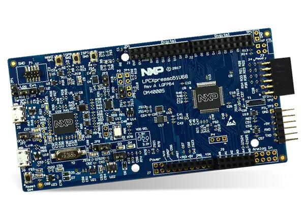
하드웨어
- 최대 150 MHz로 동작하는 LPC51U68 Cortex-M0+
- 메모리: 256 KB flash, 96 KB SRAM
- CMSIS-DAP와 J-Link 프로토콜을 지원하는 온보드 고속 USB 디버그 프로브. 온보드 LPC51U68 또는 외부 target 디버깅 가능
- 외부 디버그 프로브 선택 가능
- 3색 LED, target reset 버튼, ISP 버튼, interrupt/user 버튼
- Arduino UNO와 PMOD 호환 확장 인터페이스 및 추가 확장 포트 핀
- FTDI UART 커넥터
자세한 자료는 아래 참고 자료의 LPC51U68 SoC 웹사이트와 데이터시트를 참고하십시오.
지원 기능
lpcxpresso51u68은 다음 기능을 지원합니다.
| 인터페이스 | 컨트롤러 | 드라이버/컴포넌트 |
|---|---|---|
NVIC | on-chip | nested vector interrupt controller |
SYSTICK | on-chip | systick |
IOCON | on-chip | pinmux |
CLOCK | on-chip | clock and reset control |
GPIO | on-chip | gpio |
I2C | on-chip | i2c master/slave controller |
UART | on-chip | serial port-polling; serial port interrupt |
SPI | on-chip | SPI master |
그 밖의 하드웨어는 아직 Zephyr에서 지원하지 않습니다.
연결과 I/O
IOCON 컨트롤러로 LPC51U68 핀을 구성할 수 있습니다.
| 이름 | 기능 | 용도 |
|---|---|---|
PIO0_0 | UART | USART RX |
PIO0_1 | UART | USART TX |
PIO1_10 | GPIO | GREEN LED |
PIO0_29 | GPIO | RED LED |
PIO1_9 | GPIO | BLUE_LED |
PIO0_25 | I2C | I2C SCL |
PIO0_26 | I2C | I2C SDA |
PIO0_18 | SPI | SPI MISO |
PIO0_19 | SPI | SPI SCK |
PIO0_20 | SPI | SPI MOSI |
PIO1_1 | SPI | SPI SSEL2 |
프로그래밍과 디버깅
애플리케이션은 일반적인 Zephyr 절차로 빌드하고 플래시합니다.
디버그 프로브 구성
디버그 프로브는 보드 플래시와 디버깅에 모두 사용됩니다. 이 보드는 기본적으로 LPC-Link2 CMSIS-DAP 온보드 디버그 프로브를 사용하도록 구성되어 있습니다. 그러나 pyOCD 디버그 호스트 도구가 이 프로브를 지원하지 않으므로 다음 디버그 프로브로 재구성해야 합니다.
LPC-Link2 J-Link 온보드 디버그 프로브
J-Link 디버그 호스트 도구를 설치하고 실행 파일이 검색 경로에 있는지 확인합니다. LPC-Link2 J-Link 온보드 디버그 프로브 안내에 따라 J-Link 펌웨어를 프로그래밍합니다.
콘솔 구성
USB-to-FTDI 어댑터의 RX, TX, GND 핀을 P3 커넥터에 연결합니다. minicom, PuTTY 등 원하는 직렬 터미널에서 다음 설정을 사용합니다.
- 속도:
115200 - 데이터:
8 bits - 패리티:
None - 정지 비트:
1
플래시
hello_world 애플리케이션을 빌드하고 플래시하는 예는 다음과 같습니다.
west build -b lpcxpresso51u68 samples/hello_world
west flash
***** Booting Zephyr OS build zephyr-v2.6.0-934-g4c438c0c7d13 *****
Hello World! lpcxpresso51u68디버깅
hello_world 애플리케이션을 빌드하고 디버깅하는 예는 다음과 같습니다.
west build -b lpcxpresso51u68 samples/hello_world
west debug직렬 터미널을 열고 디버거에서 애플리케이션을 단계 실행하면 터미널에 다음 메시지가 나타납니다.
***** Booting Zephyr OS build zephyr-v2.6.0-934-g4c438c0c7d13 *****
Hello World! lpcxpresso51u68참고 자료
Source
출처
영어 원문에는 문단, 문서 지시문, 표, 코드, 코드 심벌, 경로를 그대로 보존했습니다.